NCERT Exemplar Class 12 Physics Chapter 10 Wave Optics are part of NCERT Exemplar Class 12 Physics . Here we have given NCERT Exemplar Class 12 Physics Chapter 10 Wave Optics.
NCERT Exemplar Class 12 Physics Chapter 10 Wave Optics
Multiple Choice Questions (MCQs)
Single Correct Answer Type
Question 1. Consider a light beam incident from air to a glass slab at Brewster’s angle as shown in figure.
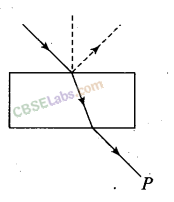
A Polaroid is placed in the path of the emergent ray at point P and rotated about an axis passing through the centre and perpendicular to the plane of the polaroid.
(a) For a particular orientation, there shall be darkness as observed through the polaroid.
(b) The intensity of light as seen through the polaroid shall be independent of the rotation.
(c) The intensity of light as seen through the polaroid shall go minimum but not zero for two orientations of the polaroid.
(d) The intensity of light as seen through the polaroid shall go minimum for four orientations of the polaroid.
Solution:
(c)
Key concept:
Brewster’s law: Brewster discovered that when a beam of unpolarised light is reflected from a transparent medium (refractive index = µ), the reflected light is completely plane polarised at a certain angle of incidence (called the angle of polarisation θ
p
).
From figure, it is clear that θ
p
+ θ
r
= 90°
Also n = tan θ
p
(Brewster’s law)
(i) For i < θ
p
or i > θ
p
Both reflected and refracted rays becomes partially polarised.
(ii) For glass θ
p
= 51° for water θ
p
= 53°
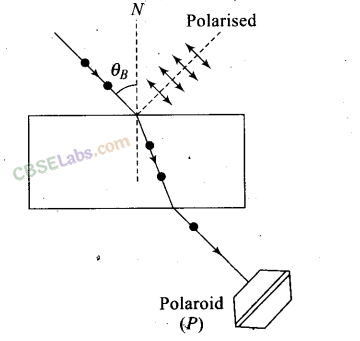
If a light beam is incident on a glass slab at Brewster’s angle, the transmitted beaiji is unpolarised and reflected beam is polarised.
In the given figure, the light beam is incident from air to the glass slab at Brewster’s angle (i
p
). The incident ray is unpolarised and is represented by dot (•). The reflected light is plane polarised represented by arrows.
As the emergent ray is unpolarised, hence intensity cannot be zero when passes through polaroid.
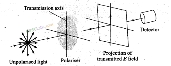
Important points:
Polarised light: The phenomenon of limiting the vibrating of electric field vector in one direction in a plane perpendicular to the direction of propagation of light wave is called polarization of light.
(i) The plane in which oscillation occurs in the polarised light is called plane of oscillation.
(ii) The plane perpendicular to the plane of oscillation is called plane of polarisation.
(iii) Light can be polarised by transmitting through certain crystals such as tourmaline or polaroids.
Polaroids: It is a device used to produce the plane polarised light. It is based on the principle of selective absorption and is more effective than the tourmaline crystal, or it is a thin film of ultramicroscopic crystals of quinine iodosulphate with their optic axis parallel to each other.
Question 2. Consider sunlight incident on a slit of width 104 Å. The image seen through the slit shall
(a) be a fine sharp slit white in colour at the centre
(b) a bright slit white at the centre diffusing to zero intensities at the edges
(c) a bright slit white at the centre diffusing to regions of different colours
(d) only be diffused slit white in colour.
Solution:
(a)
Key concept: –
Diffraction of Light is the phenomenon of bending of light around the comers of an obstacle/aperture of the size of the wavelength of light.
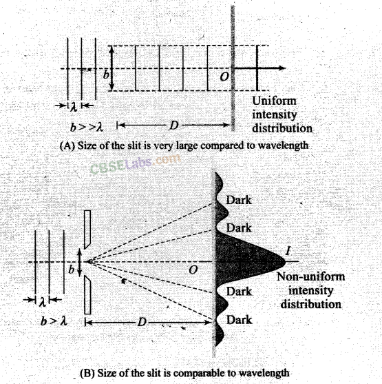
In figure (A), no diffraction phenomenon is observed as the size of slit is weary large compared to wavelength. But in figure(B), there will be diffraction of light as size of slit is compared to the wavelength of light incident.
Here in the question it is given, width of the slit
b = 104 Å = 104 x 10
-10
m = 10
-6
m = 1 pm
Wavelength of (visible) sunlight varies from 4000 Å to 8000 Å.
Hence the width of slit is comparable to that of wavelength, hence diffraction occurs with maxima at centre. So, at the centre all colours appear, i.e., mixing of colours form white patch at the centre.
Question 3. Consider a ray of light incident from air onto a slab of glass (refractive index n)
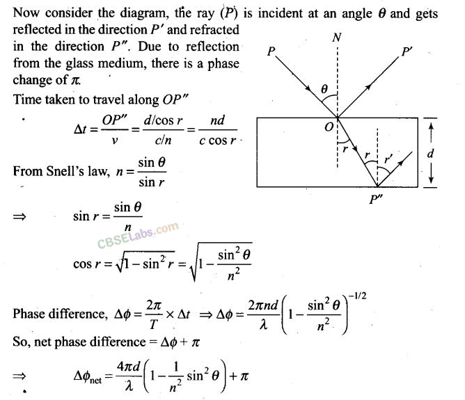
of width d, at an angle θ. The phase difference between the ray reflected by the top surface of the glass and the bottom surface is

Solution:
(a)
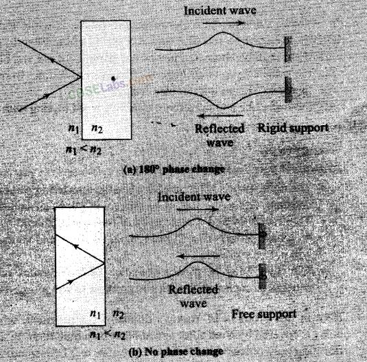
Key concept: If slab of a glass is placed in air, the wave reflected from the upper surface (from a denser medium) sutlers a sudden phase change of π, while the wave reflected from the lower surface (from a rarer medium) suffers no such phase change.
It is useful to draw an analogy between reflected light waves and the reflections of a transverse wave on a stretched string when the wave meets a boundary:
Figure (a) shows that ray reflecting from a medium of higher refractive index undergoes a 180° phase change.
Question 4. In a Young’s double-slit experiment, the source is white light. One of the holes is covered by a red filter and another by a blue filter. In this case,
(a) there shall be alternate interference patterns of red and blue
(b) there shall be an interference pattern for red distinct from that for blue
(c) there shall be no interference fringes
(d) there shall be an interference pattern for red mixing with one for blue
Solution:
(c)
Key concept:
Condition for Observing Interference
The initial phase difference between the interfering waves must remain constant. Otherwise the interference will not be sustained.
The frequency and wavelengths of two waves should be equal. If not the phase difference will not remain constant and so the interference will not be sustained.
The light must be monochromatic. This eliminates overlapping of patterns as each wavelength corresponds to one interference pattern.
Here in this problem of Young’s double-slit experiment, when one of the holes is covered by a red filter and another by a blue filter. In this case due to filtration only red and blue lights are present. In YDSE monochromatic light is used for the formation of fringes on the screen. Hence, in this case there shall be no interference fringes.
The wave front emitted by a narrow source is divided in two parts by reflection, refraction or diffraction. The coherent sources so obtained are imaginary.
Question 5. Figure shows a standard two slit arrangement with slits S
1
, S
2
, P
1
, P
2
are the two minima points on either side of P (figure).
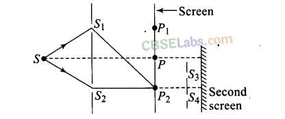
At P
2
on the screen, there is a hole and behind P
2
.is a second 2-slit arrangement with slits S
3
, S
4
and a second screen behind them.
(a) There would be no interference pattern on the second screen but it would be lighted
(b) The second screen would be totally dark
(c) There would be a single bright point on the second screen
(d) There would be a regular two slit pattern on the second screen
Solution:
(d)
Key concept:
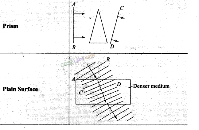
Wave front
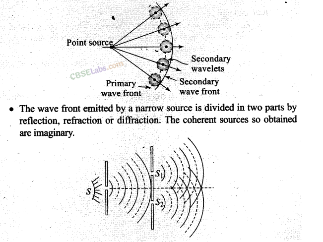
Every point on the given wave front acts as a source of new disturbance called secondary wavelets which travel in all directions with the .velocity of light in the medium.
A surface touching these secondary wavelets tangentially in the forward direction at any instant gives the new wave front at that instant. This is called secondary wave front.In the given question, there is a hole at point which is a maxima point. From Huygen’s principle, wave will propagate from the sources S
1
and S
2
. Each point on the screen will act as secondary sources of wavelets.
One or More Than One Correct Answer Type
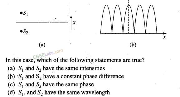
Question 6. Two sources S
1
and S
2
of intensity I
1
and I
2
are placed in front of a screen .
(a) The pattern of intensity distribution seen in the central portion is given by Fig. (b).
In this case, which of the following statements are true?
Solution:
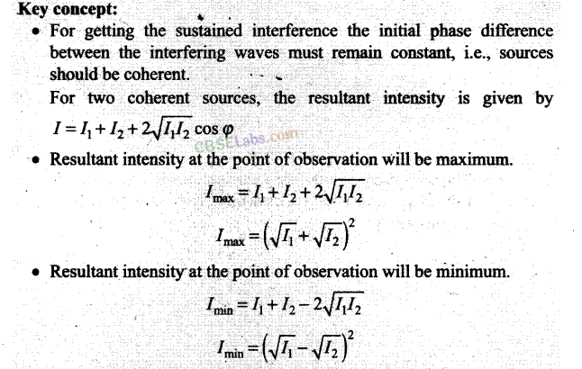
Key concept:
Question 7. Consider sunlight incident on a pinhole of width 103 Å. The image of the pinhole seen on a screen shall be
(a) a sharp white ring
(b) different from a geometrical image
(c) a diffused central spot, white in colour
(d) diffused coloured region around a sharp central white spot
Solution:
(b, d)
Key concept: Diffraction of Light can be observed only if the size of obstacle/aperture is less than the wavelength of light.
Given, width of pinhole = 103 Å = 1000 Å
We know that wavelength of sunlight ranges from 4000 Å to 8000 Å. Clearly, wavelength X < width of the slit.
Hence, light is diffracted from the hole. Due to diffraction from the slit the image formed on the screen will be different from the geometrical image.
Question 8. Consider the diffraction pattern for a small pinhole. As the size of the hole is increased
(a) the size decreases (b) the intensity increases
(c) the size increases (d) the intensity decreases
Solution:
(a,b)
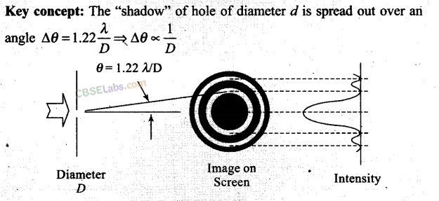
The central bright disc is known as Airy’s disc.
As the size of the hole is increased, AO will decrease and size of Airy’s disc will decrease.
As the size of the hole is increased, the width of the central maximum of the diffraction pattern of hole decreases. Since the same amount of light is now distributed over a small area, as intensity ∞ 1/area, the area is decreasing so area intensity increases.
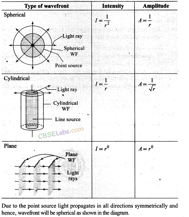
Question 9. For light diverging from a point source,
(a) the wavefront is spherical
(b) the intensity decreases in proportion to the distance squared
(c) the wavefront is parabolic
(d) the intensity at the wavefront does not depend on the distance
Solution:
(a, b)

Question 10. Is Huygen’s principle valid for longitudinal sound waves?
Solution:
Yes it can. Huygen’s principle basically states that every point wave front can be considered as a secondary source of tiny wavelets that spread out in the forward direction of the wave itself. The disturbance due to the source propagates in spherical symmetry that is in all directions. The formation of wavefront is in accordance with Huygen’s principle.
So, Huygen’s principle’is valid for longitudinal sound.waves also.
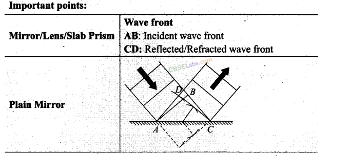
Question 11. Consider a point at the focal point of a convergent lens. Another convergent lens of short focal length is placed on the other side. What is the nature of the wavefronts emerging from the final image?
Solution:
Orientation of wave front is perpendicular to ray. The ray diagram of the situation is as shown in figure.

Parallel rays incident on lens L
1
forms the image I
2
at the focal point of the lens. This image acts as object for the lens L
2
Now, due to the converging lens L
2
, let final image formed is I which is point image. Hence the wavefront for this image will be of spherical symmetry.
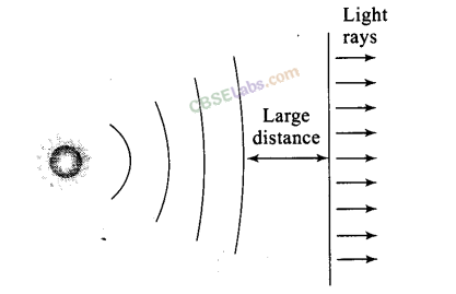
Question 12. What is the shape of the wavefront on earth for sunlight?
Solution:
The sun is at very large distance from the earth. Assuming sun as spherical, it can be considered as point source situated at infinity. We can treat it like a point object as seen from the surface of earth.
Because of large distance, the radius of wavefront can be considered as Large (infinity) and hence, wavefront is almost plane.
Question 13. Why is the diffraction of Sound waves more evident in daily experience than that of light wave?
Solution:
The frequencies of sound waves lie between 20 Hz to 20 kHz, their wavelength ranges between 15 m to 15 mm. The diffraction occurs if the wavelength of waves is nearly equal to slit width.
The wavelength of light waves is 7000 x 10
-10
m to 4000 x 10
-10
m. For observing diffraction of light we need very narrow slit width. In daily life experience we observe the slit width very near to the wavelength of sound waves as compared to light waves. Thus, the diffraction of sound waves is more evident in daily life than that of light waves.
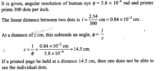
Question 14. The human eye has an approximate angular resolution of ɸ = 5.8 x 10
-4
rad and a typical photoprinter prints a minimum of 300 dpi (dots per inch, 1 inch = 2.54 cm). At what minimal distance z should a printed page be held so that one does not see the individual dots.
Solution:
It is given, angular resolution of human eye ɸ = 5.8 x 10
-4
rad and printer prints 300 dots per inch.
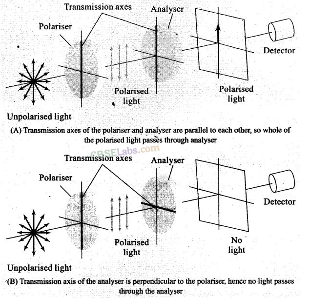
Question 15. A polaroid (I) is placed in front,of a monochromatic source. Another polariod (II) is placed in front of this polaroid (I) and rotated till no light passes. A third polaroid (III) is now placed in between (I) and (II). In this case, will light emerge from (II). Explain.
Solution:
A polaroid (I) is placed in front of a monochromatic source. Another polariod (II) is placed in front of this polaroid (I) when the pass axis of (II) is parallel to (I), light passes through polaroid-II is unaffected.
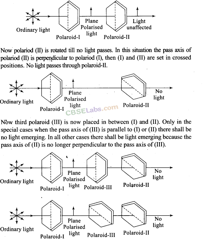
Now polariod (II) is rotated till no light passes. In this situation the pass axis of polariod (II) is perpendicular to polariod (I), then (I) and (II) are set in crossed positions. No light passes through polaroid-II.
Now third polaroid (III) is now placed in between (I) and (II). Only in the special cases when the pass axis of (III) is parallel to (I) or (II) there shall be no light emerging. In all other cases there shall be light emerging because the pass axis of (II) is no longer perpendicular to the pass axis of (III).
Short Answer Type Questions
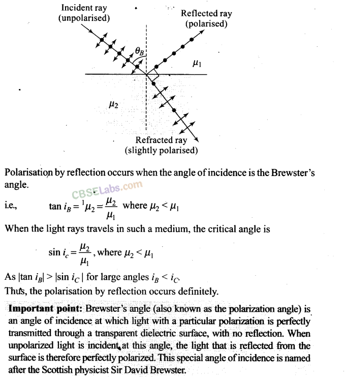
Question 16. Can reflection result in plane polarised light if the light is incident on the interface from the side with higher refractive index?
Solution:
If angle of incidence is equal to Brewster’s angle, the transmitted light is slightly polarised and reflected light is plane polarised.
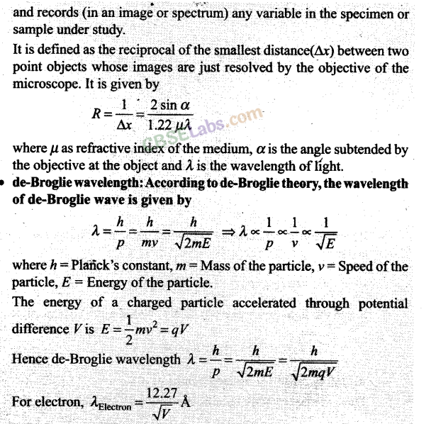
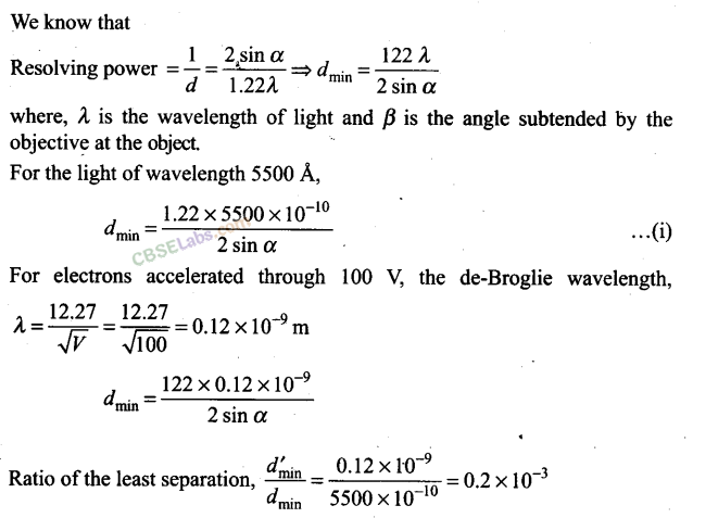
Question 17. For the same objective, find the ratio of the least separation between two points to be distinguished by a microscope for light of 5000 Å
and electrons accelerated through 100 V used as the illuminating substance.
Solution:
Key concept:
• Resolving power is the ability of an imaging device to separate (i.e., to see as distinct) points of an object that are located at a small angular distance or it is the power of an optical instrument to separate far – away objects, that are close together, into individual images. The term resolution or minimum resolvable distance is the minimum distance between distinguishable objects in an image, although the term is loosely used by many users of microscopes and telescopes to describe resolving power. In scientific analysis, in general, the term “resolution” is used to describe the precision with which any instrument measures Ratio of the least separation,
For electrons accelerated through 100 V, the de-Broglie wavelength, 12.27
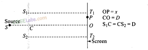
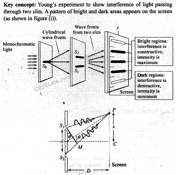
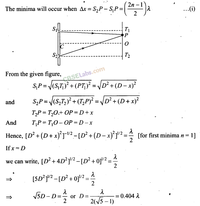
Question 18. Consider a two slit interference arrangements (figure) such that the distance of the screen from the slits is. half the distance between the slits. Obtain the value of D in terms of X such that the first minima on the screen falls at a distance D from the centre O.
Solution:

Long Answer Type Questions
Question 19.
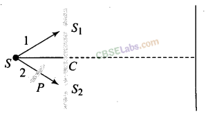
Figure shown has a two sift arrangement with a source which emits unpolarised light. P is a polariser with axis whose direction is not given. If I
0
is the intensity of the principal maxima when no polariser is present, calculate in the present case, the intensity of the principal maxima as well as of the first minima.
Solution:
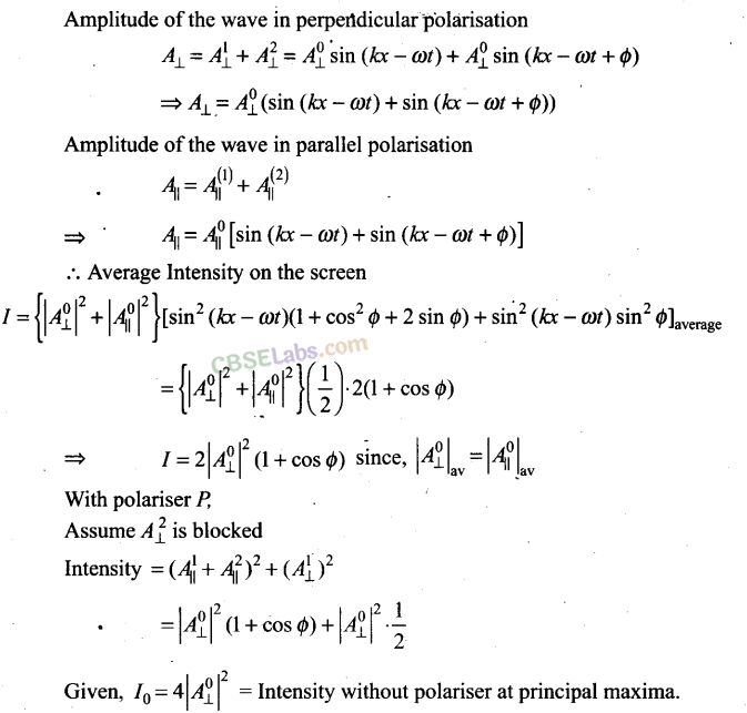
The resultant amplitude of wave reaching on screen will be the sum of amplitude of either wave in perpendicular and parallel polarisation.

Question 20.
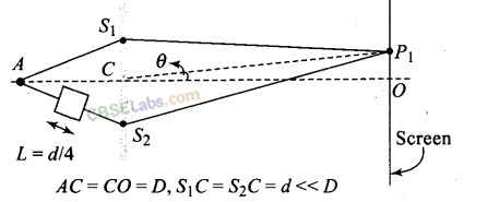
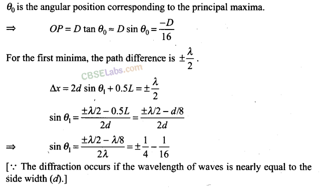
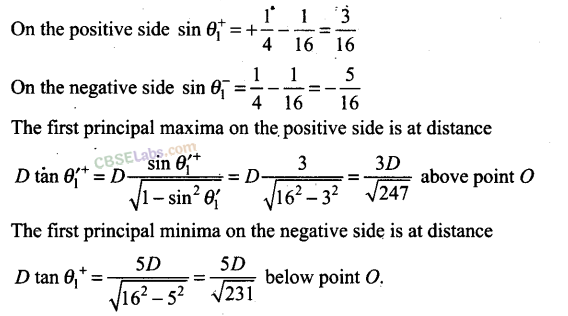
A small transparent slab containing material of µ = 1.5 is placed along AS
2
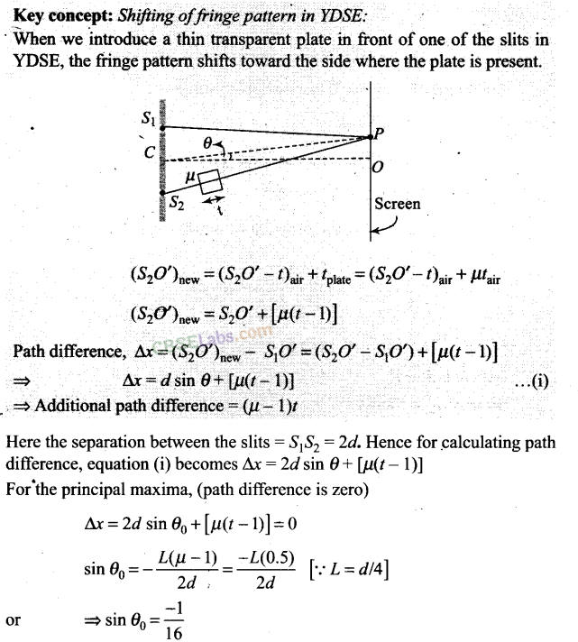
(figure). What will be the distance from O of the principal maxima and of the first minima on either side of the principal maxima obtained in the absence of the glass slab?
Solution:
Question 21.
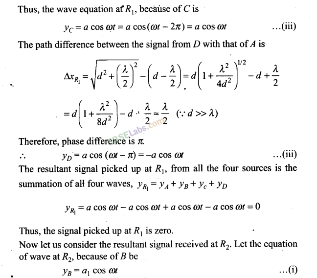
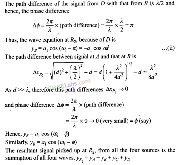
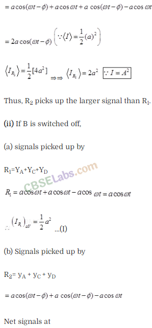
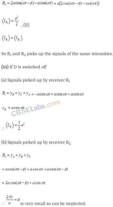
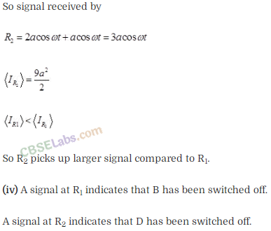
Solution:
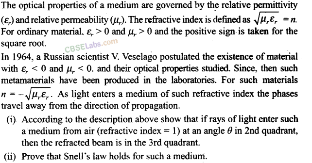
Question 22.
Solution:

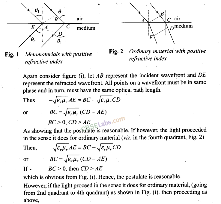
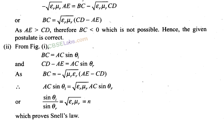
NCERT Exemplar Class 12 Physics Solutions
- Chapter 1 Electric Charges and Fields
- Chapter 2 Electrostatic Potential and Capacitance
- Chapter 3 Current Electricity
- Chapter 4 Moving Charges and Magnetism
- Chapter 5 Magnetism and Matter
- Chapter 6 Electromagnetic Induction
- Chapter 7 Alternating Current
- Chapter 8 Electromagnetic Waves
- Chapter 9 Ray Optics and Optical Instruments
- Chapter 10 Wave Optics
- Chapter 11 Dual Nature of Radiation and Matter
- Chapter 12 Atoms
- Chapter 13 Nuclei
- Chapter 14 Semiconductor Electronics: Materials, Devices and Simple Circuits
- Chapter 15 Communication Systems