Important Questions for Class 12 Physics Chapter 3 Current Electricity Class 12 Important Questions
Current Electricity Class 12 Important Questions Very Short Answer Type
Question 1.
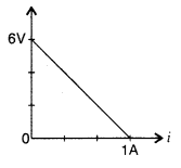
The plot of the variation of potential difference across a combination of three identical cells in series, versus current is as shown in the figure. What is the emf of each cell? (Delhi 2008)
Answer:
Total emf of three cells in series = P.D corresponding to zero current = 6V
∴ The emf of each cell = \(\frac{6}{3}\) = 2V
Question 2.
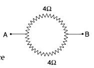
A wire of resistance 8R is bent in the form of a circle. What is the effective resistance between the ends of a A diameter 2AB? (Delhi 2008)
Answer:
The effective resistance between A and BO

Question 3.
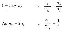
Two conducting wires X and Y of same diameter across a battery. If the number density of electro in X is twice that in Y, find the ratio of drift velocity of electrons in the two wires. (All India 2008)
Answer:
Question 4.
A resistance R is connected across a cell of emf ε and internal resestance r. A potentiometer now measures the potential difference between the terminals of the cell as V. write the expression for ‘r’ in terms of ε, V and R. (Delhi 2011)
Answer:

Question 5.
When electrons drift in a metal from lower to higher potential, does it mean that all the free electrons of the metal are moving in the same direction? (Delhi 2012)
Answer:
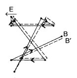
No, only the drift velocities of the electrons are superposed over their random (haphazard) thermal velocities. The solid line shows the random path followed by a free electron in the absence of an external field.
The electron proceeds from A to B, making six collisions on its path. The dotted curve shows how the random motion of the same electron gets modified when an electric field is applied.
Question 6.
Show on a graph the variation of resistivity with temperature for a typical semiconductor . (Delhi 2012)
Answer:
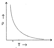
Resistivity of a semi conductor decreases rapidly with temperature.
Question 7.
Two wires of equal length, one of copper and the other of manganin have the same resistance. Which wire is thicker? (All India 2012)
Answer:
![]()
For both wires R and l are same and ρ copper < p manganin.
∴ A copper < A manganin
i.e. Manganin wire is thicker than copper wire.
Question 8.
A 10 v battery of negligible internal resistance is connected across a 200 V battery and a resistance of 38Ω as shown in the figure. Find the value of the current in circuit. (Delhi 2013)
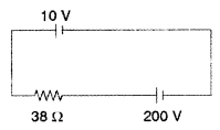
Answer:
Applying Kirchhof s rule, we get 200 -10 = 190 V
![]()
Question 9.
A 5 V battery of negligible internal resistance is connected across a 200 V battery and a resistance of 39 Ω as shown in the figure. Find the value of the current (Delhi 2013)
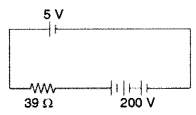
Answer:
![]()
Question 10.
The emf of a cell is always greater than its terminal voltage. Why? Give reason. (Delhi 2013)
Answer:
Emf is the p.d. when no current is drawn. When current is drawn, there will be potential drop across the internal resistance of the cell. So, terminal voltage will be less than the emf.
Question 11.
A cell of emf ‘E’ and internal resistance ‘r’ draws a current ‘I’. Write the relation between terminal voltage ‘V’ in terms of E, I and r. (Delhi 2013)
Answer:
V = E – I
Question 12.
Two identical cells, each of emf E, having negligible internal resistance, are connected in parallel with each other across an external resistance R. What is the current through this resistance ?
Answer:
![]()
[When cells are connected in parallel, emf remains unchanged]
Question 13.
Why is the terminal voltage of a cell less than its emf? (Comptt. All India 2013)
Answer:
Terminal voltage of a cell is less than emf because some curent, however small, may be is drawn to measure terminal voltage due to internal resistance of the cell.
Question 14.
Two students A and B were asked to pick a resistor of 15 kΩ from a collection of carbon resis-tors. A picked a resistor with bands of colours : brown, green, orange while B chose a resistor with bands of black, green, red. Who picked the correct resistor? (Comptt. All India 2013)
Answer:
Student ‘A’ picked up the correct resistor of 15 kΩ.
Question 15.
Define the term ‘Mobility’ of charge carriers in a conductor. Write its S.I. unit. (Delhi 2014)
Answer:
Mobility of charge carriers is defined as the magnitude of the drift velocity per unit electric field E.

Question 16.
Show variation of resistivity of copper as a function of temperature in a graph. (Delhi 2014)
Answer:
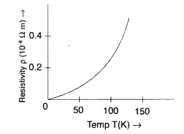
Question 17.
Define the term ‘electrical conductivity’ of a metallic wire. Write its S.I. unit. (Delhi 2014)
Answer:
Conductivity. The reciprocal of the resistivity of the material of a conductor is called its conductivity ‘σ’
![]()
The SI unit of conductivity is Ohm
-1
metre
-1
(Ω
-1
im
-1
’).
Question 18.
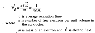
Define the term ‘drift velocity’ of charge carriers in a conductor and write its relationship with the current flowing through it. (Delhi 2014)
Answer:
Drift velocity. It is the velocity with which a free electron in the conductor gets drifted under the influence of the applied external electric field
Question 19.
How does the random motion of free electrons in a conductor get affected when a potential difference is applied across its ends? (Comptt. Delhi 2014)
Answer:
Random motion of free electrons gets directed towards the point at a higher potential.
Question 20.
State the underlying principle of a potentiometer. (Comptt. Delhi 2014)
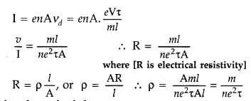
Answer:
When a constant current flows through a wire of uniform cross-section and of uniform composition, the potential difference across any length of wire is directly proportional to its length, i.e.,
V
l
\(\infty\) l
Question 21.
Write the expression for the drift velocity of charge carriers in a conductor of length T across which a potential difference ‘V’ is applied. (Comptt. All India 2014)
Answer:

Question 22.
How does one explain increase in resistivity of a metal with increase of temperature? (Comptt. All India 2014)
Answer:
With increase in temperature, the relaxation time (average time between successive collisions) decreases and hence resistivity increases. Also,
![]()
resistivity increases, as x decreases with increase in temperature.
Question 23.
Graph showing the variation of current versus voltage for a material GaAs is shown in the figure. Identify the region of
(i) negative resistance
(ii) where Ohm’s law is obeyes (Delhi 2014)
versus for a GaAs is in the Identify the region of
Answer:
DE : Negative resistance region.
AB : Where Ohm’s law is obeyed.
Question 24.
I – V graph for a metallic wire at two different temperatures, T
1
and T
2
is as shown in the figure. Which of the two temperatures is lower and why? (All India 2015)
Answer:
The temperature T
1
is lower. Larger the slope of V-I graph, smaller the resistance. As the resistance of a metal increases with the increase of temperature, resistance at temperature T
1
is lower.
Question 25.
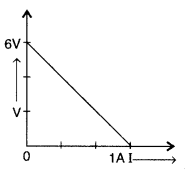
The plot of the variation of potential difference A across a combination of three identical cells in series, versus current is shown along the question. What is the emf and internal resistance of each cell? (All India 2016)
Answer:

(From the graph, current is 1A corresponding to V = 0)
Question 26.
Why is a potentiometer preferred over a voltmeter for determining the emf of a cell? (Comptt. Delhi 2016)
Answer:
Potentiometer does not draw any (net) current from the cell; while Voltmeter draws some current from cell, when connected across it, hence it measures terminal voltage. It is why a potentiometer is preferred over a voltmeter to measure emf.
Question 27.
Nichrome and copper wires of same length and same radius are connected in series. Current I is passed through them. Which wire gets heated up more? Justify your answer. (Outside Delhi 2017)
Answer:
Nichrome :
Nichrome wire gets heated up more because of higher resistivity of nichrome.
Resistivity
NI
> Resistivity
Cu
Question 28.
Define the conductivity of a conductor. Write its SI unit. (Comptt. Outside Delhi 2017)
Answer:
Conductivity is defined as the reciprocal of resistivity, i.e., σ = \(\frac{1}{\rho}\)
Its SI unit is S(Siemen)
Current Electricity Class 12 Important Questions Short Answer Type I
Question 29.
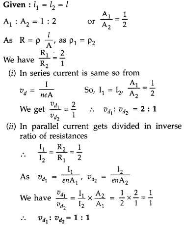
Two metallic wires of the same material have the same length but cross-sectional area is in the ratio 1 : 2. They are connected
(i) in series and
(ii) in parallel. Compare the drift velocities of electrons in the two wires in both the cases (i) and (ii). (All India 2008)
Answer:
Question 30.
Derive an expression for the resistivity of a good conductor, in terms of the relaxation time of electrons. (All India 2008)
Answer:
Drift speed gained by an electron under the effect of electric field \(\overrightarrow{\mathrm{E}}\) in a conductor is
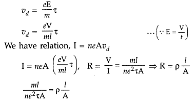
\(\rho=\frac{m}{n e^{2} \tau}\) between resistivity and relaxation time of electrons.
Question 31.
Using the mathematical expression for the conductivity of a material, explain how it varies with temperature for
(i) semiconductors,
(ii) good conductors. (All India 2008)
Answer:
Conductivity σ = \(\frac{n e^{2} \tau}{m}\)
(i) Semiconductors: With increase in temperature, conductivity of semiconductor increases. It is due to increase in V. It dominates the effect caused by decrease in ‘x’.
(ii) Good conductors : With increase in temperature, conductivity of good conductors decreases. It is due to decrease in the value of relaxation time. The effect of increased value of V is negligible.
Question 32.
A cell of emf ‘E’ and internal resistance V is connected across a variable resistor ‘R’. Plot a graph showing the variation of terminal potential ‘V’ with resistance R.
Predict from the graph the condition under which ‘V’ becomes equal to ‘E’. (Delhi 2009)
Answer:
(i) V = ε – Ir gives the terminal voltage and can be plotted as shown in Figure 1.
(ii) The graph between V and R, is shown in Figure 2.
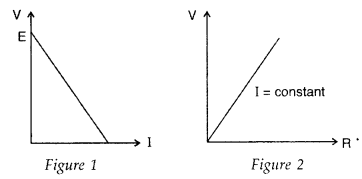
V becomes E when no current is down.
Question 33.
Derive an expression for drift velocity of free electrons in a conductor in terms of relaxation time. (Delhi 2009)
Answer:
In the absence of electric field the electrons motion is random and the net velocity is zero. In the presence of electric field, they tend to flow opposite to that of the electric field in the conduction. If an electric field ‘E’ is applied across a length l of the conductor, the electrons will experience an acceleration, a = \(\frac{e \mathrm{E}}{m}\).
If the average time for the acceleration is x, the velocity required is

Question 34.
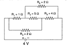
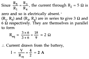
Calculate the current drawn from the battery in the given network. (All India 2009)
Answer:
Question 35.
Define current sensitivity and voltage sensitivity of a galvanometer. Increasing the current sensitivity may not necessarily increase the voltage sensitivity of a galvanometer. Justify. (All India 2009)
Answer:
Current sensitivity is defined as the deflection produced in the galvanometer when unit current is passed through its coil.

Voltage sensitivity is defined as the deflection produced in the galvanometer when unit voltage is applied across the coil of the galvanometer.

Since V
s
= \(\frac{\mathrm{I}_{\mathrm{s}}}{\mathrm{R}}\), increase in current sensitivity may
not necessarily increase the voltage sensitivity. It may be affected by the resistance used.
Question 36.
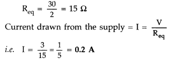
A wire of 15 Ω resistance is gradually stretched to double its original length. It is then cut into two equal parts. These parts are then connected in parallel across a 3.0 volt battery. Find the current drawn from the battery. (All India 2009)
Answer:
R = 15 Ω
On stretching to double its original length, the resistance becomes R
1
= 60 Ω, as on stretching volume is constant and R\(\alpha\) l
2
.
The two cut parts will have a resistance of 30 Ω each as they are connected in parallel, the
Question 37.
A wire of 20 Ω resistance is gradually stretched to double its original length. It is then cut into two equal parts. These parts are then connected in parallel across a 4.0 volt battery. Find the current drawn from the battery. (All India 2009)
Answer:
On stretching, the resistance of the wire will get to four times, i.e., 80 Ω as volume is constant and
R \(\alpha\) l
2
.
So the two equal parts will have a resistance of 40 Ω each.
When connected in parallel, the equivalent resistance will be 20 Ω

Question 38.
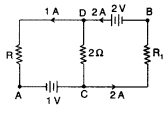
In the given circuit, assuming point A to be at zero potential, use Kirchhoff’s rules to determine the potential A at point B. (All India 2011)
Answer:
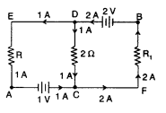
Applying Kirchhoff’s law by moving along ACDE,
we get,
Question 39.
In the meter bridge experiment, balance point was observed at J with AJ = l.
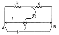
(i) The values of R and X were doubled and then interchanged. What would be the new position of balance point?
(ii) If the galvanometer and battery are interchanged at the balance position, how will the balance point get affected? (All India 2011)
Answer:
(i) Balance point will change from l to (100 – l),

(ii) From the principle of Wheatstone bridge
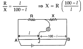
Hence, the galvanometer and cell are interchanged, the condition for a balance bridge is still satisfied. Therefore, the galvanometer will not show any deflection.
Question 40.
A cell of emf E and internal resistance r is connected to two external resistances R
1
and R
2
and a perfect ammeter. The current in the circuit is measured in four different situations:
(i) without any external resistance in the circuit
(ii) with resistance R
2
only
(iii) with R
1
and R
2
in series combination
(iv) with R
1
and R
2
in parallel combination
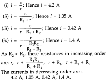
The currents measured in the four cases are 0.42A, 1.05A, 1.4A and 4.2A, but not necessarily in that order. Identify the currents corresponding to the four cases mentioned above.
Answer:
Question 41.
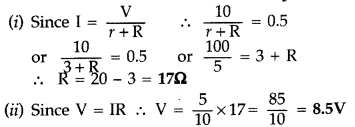
A battery of emf 10 V and internal resistance 3Ω is connected to a resistor. If the current in the circuit is 0.5 A, find
(i) the resistance of the resistor;
(ii) the terminal voltage of the battery. (Comptt. Delhi 2012)
Answer:
Question 42.
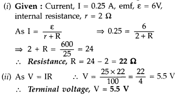
A battery of emf 6 V and internal resistance 2Ω is connected to a resistor. If the current in the circuit is 0.25 A, find
(i) the resistance of the resistors;
(ii) the terminal voltage of the battery. (Comptt. Delhi)
Answer:
Question 43.
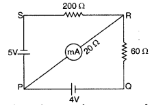
The network PQRS, shown in the circuit diagram, has the batteries of 4 V and 5 V and negligible internal resistance. A milliammeter of 20 Ω resistance is connected between P and R. Calculate the reading in the milliammeter. (Comptt. All India 2012)
Answer:
Applying loop rule to loop PQRP
-4 = 60(I – I
1
) – 20 I
1
= 0
or – 4 = 60I – 60I
1
– 20I
1
or 20I
1
-15 I = 1 …[+ by 4 …(i)]
Applying loop Yule to loop PRSP, we get
-5 + 200 I + 20 I
1
= 0
4I
1
+ 40 I = 1 …[+ by 5 …(ii)]
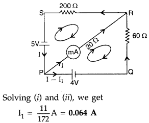
∴ Reading of milliammeter = 0.064 A
Question 44.
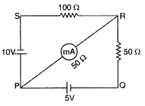
The network PQRS, shown m the circuit diagram, has the batteries of 5 V and 10 V and negligible internal resistance. A milliammeter of 50Ω resistance is connected between P and R. Calculate the reading in the milliammeter. (Comptt. All India 2012)
Answer:
Applying loop rule to loop PSRP
-10 + 100 I + 50 I
1
= 0
or 100 I + 50 I
1
= 10
or 10 I + 5 I
1
= 1 …[+ by 10 …(i)
Applying loop rule to loop PRQP
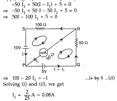
Reading in milliammeter = 0.08A
Question 45.
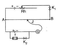
State the principle of a potentiometer. Describe briefly, with the help of a circuit diagram, how this device is used to compare the emf’s of two cells. (Comptt. All India 2012)
Answer:
Potentiometer : A potentiometer is a device used to measure potential difference.

Principle : The basic principle of a potentiometer is that when a constant current flows through a wire of uniform cross-sectional area and composition, the potential drop across any length of the wire is directly proportional to that length.
![]()
…where [K is called potential gradient
Close the key K
1
. A constant current flows through the potentiometer wire. With key K
2
kept open, move the jockey along AB till it balances the emf e of the cell. Let l, be the balancing length of the wire. If K is the potential gradient, then emf of the cell will be
![]()
With the help of resistance box R.B, introduce a resistance R and close key K
2
. Find the balance point for the terminal potential difference V of the cell. If l
2
is the balancing length, then

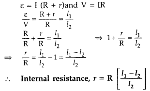
Let r be the internal resistance of the cell ε = I (R + r) and V = IR
Question 46.
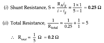
An ammeter of resitance 1 Ω can measure current upto 1.0 A
(i) What must be the value of the shunt resistance to enable the ammeter to measure upto 5.0 (A)?
(ii) What is the combined resistance of the ammeter and the shunt? (Delhi 2013)
Answer:
Question 47.
Explain the term ‘drift velocity’ of electrons in a conductor. Hence obtain the expression for the current through a conductor in terms of ‘drift velocity’
Answer:
Definition : Drift velocity is defined as the velocity with which fress electrons in a conductor get drifted in a direction opposite to the direction of the applied field. Its unit is m
-1
s and dimensions [LT
-1
]
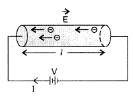
Expression : The magnitude of electric field set up across the conductor is given by
E = \(\frac{\mathrm{V}}{l}\)
Let n be the number of free electrons per unit volume of the conductor.
Then, total number of free electrons in the conductor
= n × Volume of the conductor
Hence, Q = (nAl)e
Time taken by the charge to cross the conductor length l is given by

Question 48.
Write the expression for the current in a conductor of cross-sectional area A in terms of drift velocity. (Comptt. All India 2013)
Answer:
Drift velocity. Drift velocity is defined as the velocity of the free electrons with which they get drifted towards the positive terminal under the influence of the external electric field. The drift velocity of electron is of the order of 10
-5
m/sec. Expression for current in terms of drift velocity is :
![]()
Expression : Consider a conductor of length l and of uniform cross-section area A .
∴ Volume of the conductor = Al
If n is the number of the conductors, then total number of free electrons in the conductor = Aln
If e is the charge on ” each electron, then
total charge on all A the free electrons in the conductor, q = Alne
The electric field set up across the conductor of potential difference V is given by,
![]()
![]()
Due to this field, the free electrons present in the conductor will begin to move with a drift velocity v
d
towards the positive terminal of the battery
∴ Time taken by free electrons to cross the conductor,

SinceA, n and e are constants,
![]()
Therefore, the current flowing through a conductor is directly proportional to the drift velocity.
Question 49.
Describe briefly, with the help of a circuit diagram, how a potentiometer is used to determine the internal resistance of a cell.
(All India 2013)
Answer:
The apparatus is set up as per circuit diagram drawn here.
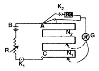
The cell (emf ε), whose internal resistance (r) is to be determined, is connected across a resistance box through a key K
2
, as shown in the figure. With key K
2
is open, balance is obtained at length l
1
(AN
1
), then
![]()
When key K
2
is closed, the cell sends a current (I) through the resistance box (R). If V is the terminal potential difference of the cell and balance is obtained at length l
2
(AN
2
)
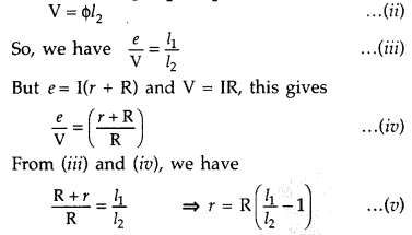
Using equation (v) we can find internal resistance of the cell.
Question 50.
Write a relation between current and drift veloc¬ity of electrons in a conductor. Use this relation to explain how the resistance of a conductor changes with the rise in temperature. (Comptt. Delhi 2013)
Answer:
Relation between current and drift velocity :
![]()
On increasing temperature, the resistance of the conductor increases due to increase in frequent collisions of electrons with each other, resulting into decrease in the drift velocity.
Question 51.
Use Kirchhoff’s rules to determine the value of the current I
1
flowing in the circuit shown in the figure. (Comptt. Delhi 2013)
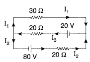
Answer:
Using Kirchoff’s first law at junction E, we get
I
3
= I
3
+ I
2
In loop ABCDA, using Kirchoff’s second law, we get
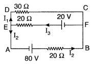
80 – 20 I
2
+ 30 I
1
= 0
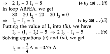
So (-) sign of current indicates that the direction of current is opposite to that as shown in the circuit diagram.
Question 52.
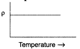
Draw a graph showing variation of resistivity with temperature for nichrome. Which property of nichrome is used to make standard resistance coils? (Comptt. All India 2013)
Answer:
Temperature coefficient of resistivity (α) is very small for nichrome.
Question 53.
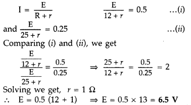
A battery of emf E and internal resistance r when connected across an external resistance of 12 ft, produces a current of 0.5 A. When connected across a resistance of 25 ft, it produces a current of 0.25 A. Determine
(i) the emf and
(ii) the internal resistance of the cell. (Comptt. All India 2013)
Question 54.
Define mobility of a charge carrier. Write the relation expressing mobility in terms of relaxation time. Give its SI unit. (Comptt. All India 2013)
Answer:
Mobility. Mobility of electron p is defined as the magnitude of the drift velocity per unit electric field E

Question 55.
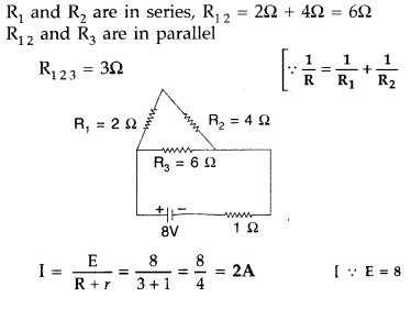
A uniform wire of resistance 12 Ω is cut into three pieces so that the ratio of the resistances R
1
: R
2
: R
3
= 1 : 2 : 3 and the three pieces are connected to form a triangle across which a cell of emf 8V and internal resistance
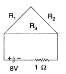
1 Ω is connected as shown. Calculate the current through each part of the circuit. (Comptt. All India 2013)
Answer:
Question 56.
State Kirchhoff’s rules. Explain briefly how these rules are justified. (Delhi 2014)
Answer:
Kirchhoff’s rules.
- Kirchhoff’s junction rule : At any junction, the sum of the currents entering the junction is equal to the sum of currents leaving the junction.
- Kirchhoff’s loop rule : The algebraic sum of changes in potential in any closed loop involving resistors and cells is zero.
These two laws are justified on the basis of law of conservation of charge and the law of conservation of energy respectively.
Question 57.
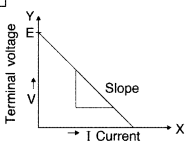
A cell of emf ‘E’ and internal resistance V is connected across a variable resistor ‘R’. Plot a graph showing variation of terminal voltage ‘V’ of the cell versus the current ‘I’. Using the plot, show how the emf of the cell and its internal resistance can be determined. (All India 2014)
Answer:
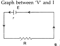
Intercept of Y-axis will give the value of ‘E’; while the slope of the line will give the value of internal resistance.
Question 58.
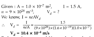
Estimate the average drift speed of conduction electrons in a copper wire of cross-sectional area 1.0 × 10
-7
m
2
carrying a current of 1.5 A. Assume the density of conduction electrons to be 9 × 10
28
m
-3
. (All India 2014)
Answer:
Question 59.
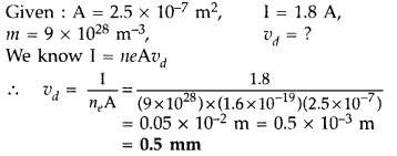
Estimate the average drift speed of conduction electrons in a copper wire of cross-sectional area 2.5 × 10
-7
m
2
carrying a current of 1.8 A. Assume the density of conduction electrons to be 9 × 10
28
m
-3
. (All India 2014)
Answer:
Question 60.
Estimate the average drift speed of conduction electrons in a copper wire of cross-sectional area 2.5 × 10
-7
m
2
carrying a current of 2.7 A. Assume the density of conduction electrons to be 9 × 10
28
m
-3
. (All India 2014)
Answer:
0.75 × 10
-3
ms
-1
Question 61.
Draw a plot showing the variation of resistivity of a
(i) conductor and
(ii) semiconductor, with the increase in temperature.
How does one explain this behaviour in terms of number density of charge carriers and the relaxation time? (Comptt. Delhi 2014)
Answer:
(i) For conductor :
(ii) For semiconductor :
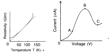
(iii) Behaviour :
![]()
In conductors, average relaxation time decreases with increase in temperature, resulting in an increase in resistivity.
In semiconductors, the increase in number density (with increase in temperature) is more than the decrease in relaxation time; the net result is, therefore, a decrease in resistivity.
Question 62.
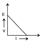
Distinguish between emf (ε) and terminal voltage (V) of a cell having internal resistance r. Draw a plot showing the variation of terminal voltage (V) vs the current (I) drawn from the cell. Using this plot, how does one determine the internal resistance of the cell?
– (Comptt All India 2014)
Answer:
emf is the potential difference between two terminals of the cell, when no current is drawn from the cell I while
• terminal voltage is the potential difference between two terminals when current passes through it.
• negative slope of the graph gives internal resistance.
Question 63.
Use Kirchhoff’s rules to obtain conditions for the balance condition in a Wheatstone bridge. (Delhi 2015)
Answer:
Conditions for the balance condition in a Wheatstone bridge :
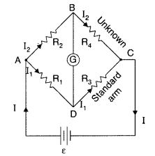
Applying Kirchhoff’s loop rule to closed loop ADBA,
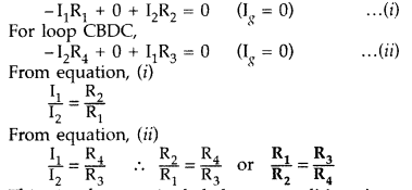
This is the required balance condition in a Wheatstone bridge arrangement.
Question 64.
Use Kirchhoff’s rules to determine the potential difference between the points A and D when no current flows in the arm BE of the electric network shown in the figure.
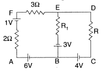
Answer:
Let us consider the loop ABED.
Using Kirchhoff’s second law, we have

Question 65.
Calculate the current drawn from the battery by the network of resistors shown in the figure. (Comptt. All India 2015)
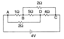
Answer:
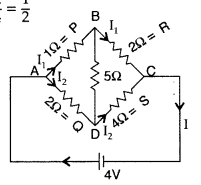
Given : Circuit diagram can be rearranged as shown below :
It forms a wheatstone’s bridge
![]()
It is the condition of null point when no current flows through BD arm, i.e. 5 Ω.
Resistances P = (1 Ω) and R = (2 Ω) are in series;
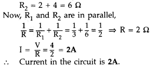
Similarly, Resistances Q = (2 Ω) and S in series,
Question 66.
Using the concept of drift velocity of charge carriers in a conductor, deduce the relationship between current density and resistivity of the conductor. (Comptt. Delhi 2015)
Answer:
The drift velocity is given by,
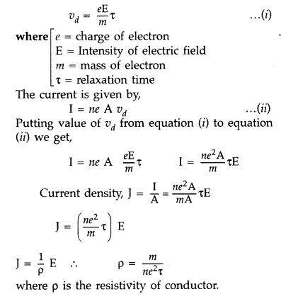
Question 67.
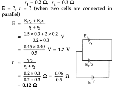
Two cells of emfs 1.5 V and 2.0 V having internal resistance 0.2 Ω and 0.3 Ω respectively are connected in parallel. Calculate the emf and internal resistance of the equivalent cell.(Delhi 2016)
Answer:
Given : E
1
= 1.5 V, E
2
= 2.0 V,
Question 68.
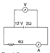
A battery of emf 12V and internal resistance 2 Ω is connected to a 4 Ω resistor as shown in the figure.
(a) Show that a voltmeter when placed across the cell and across the resistor, in turn, gives the
(b) To record the voltage and the current in the circuit, why is voltmeter placed in parallel and ammeter in series in the circuit? (All India)
Answer:
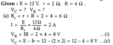
We find from the equations (i) and (ii), the voltmeter gives the same reading, i.e. 8 V.
(b) An ammeter is connected in series because same current is flowing in the circuit, while voltmeter is connected in parallel to measure potential difference across two points in the circuit.
Question 69.
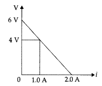
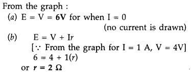
The figure shows a plot of terminal voltage ‘V’ versus the current ‘i’ of a given cell. Calculate from the graph
(a) emf of the cell and
(b) internal resistance of the cell. (Comptt. Outside Delhi 2017)
Answer:
Question 70.
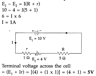
A cell of emf 4 V and internal resistance 1 Ω is connected to a d.c. source of 10 V through a resistor of 5 Ω. Calculate the terminal voltage across the cell during charging.
Answer:
Current Electricity Class 12 Important Questions Short Answer Type II
Question 71.
Prove that the current density of a metallic conductor is directly proportional to the drift speed of electrons. (Delhi 2008)
Or
Derive an expression for the current density of a conductor in terms of the drift speed of electrons. (All India 2008)
Answer:
Suppose a potential difference V is applied across a conductor of length l and of uniform cross-section A. The electric field E set up inside the conductor is given by
E = \(\frac{V}{l}\)
Under the influence of field \(\overrightarrow{\mathrm{E}}\), the free electrons begin to drift in the opposite direction \(\overrightarrow{\mathrm{E}}\) with an average drift velocity v
d
.
Let the number of electrons per unit volume or electron density = n
Charge on an electron = e
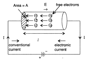
No. of electrons in length l of the conductor = n x volume of the conductor = n × Al
Total charge contained in length l of the conductor is
q = enAl … (i)
All the electrons which enter the conductor at the right end will pass through the conductor at the left end in time,
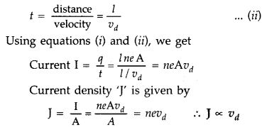
Hence the current density of a metallic conductor is directly proportional to the drift speed of electrons.
Question 72.
A number of identical cells n, each of emf e, internal resistance r connected in series are charged by a d.c. source of emf elr using a resistor R.
(i) Draw the circuit arrangement.
(ii) Deduce the expressions for
(a) the charging current and
(b) the potential difference across the combination of the cells. (Delhi 2008)
Answer:
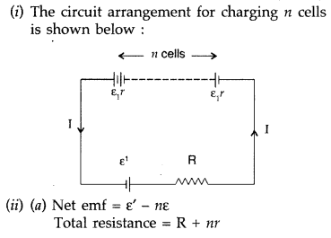
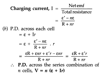
Question 73.
A potentiometer wire of length 1 m is connected to a driver cell of emf 3 V as shown in the figure. When a cell of 1.5 V emf is used in the secondary circuit, the balance point is found to be 60 cm. On replacing this cell and using a cell of unknown emf, the balance point shifts to 80 cm.
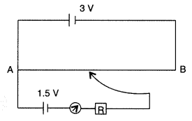
(i) Calculate unknown emf of the cell.
(ii) Explain with reason, whether the circuit works, if the driver cell is replaced with a cell of emf 1 V.
(iii) Does the high resistance R, used in the secondary circuit affect the balance point? Justify your answer. (Delhi 2008)
Answer:
![]()
(ii) The circuit will not work. If emf of auxiliary battery is greater than the emf of the driver cell of the potentiometer, there will be no balance point on the wire AB. The maximum potential drop across the wire will be of 1 V and will not be able to balance 1.5 V emf.
(iii) No, the balance point is not affected by the high resistance R because no current flows through the cell at the balance point.
Question 74.
Define resistivity of a conductor. Plot a graph showing the variation of resistivity with temperature for a metallic conductor. How does one explain such a behaviour, using the mathematical expression of the resistivity of a material. (Delhi 2008)
Answer:
(i) Resistivity of conductor : It is the resistance of a conductor of unit length and unit area of cross-section.

(ii) Variation of resistivity with temperature :
The resistivity of a material is given by
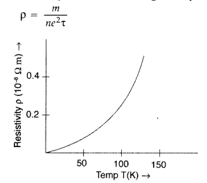
On increasing temperature, average speed of drifting electrons increases. As a result collisions are more frequent. Average relaxation time τ decreases, hence ‘ρ’ increases.
Question 75.
(i) Calculate the equivalent resistance of the given electrical network between points A and B.
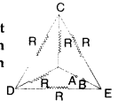
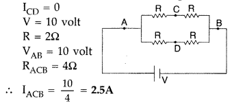
(ii) Also calculate the current through CD and ACB, if a 10 V d.c. source is connected between A and B, and the value of R is assumed as 2 Ω. (All India 2008)
Answer:
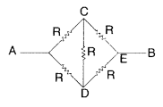
(i) Equivalent circuit of the given problem is shown in the given diagram. The simplified circuit is equivalent to a balanced wheatstone bridge.
Hence there will be no current in arm CD,
(ii) Being a balanced wheatstone bridge
Question 76.
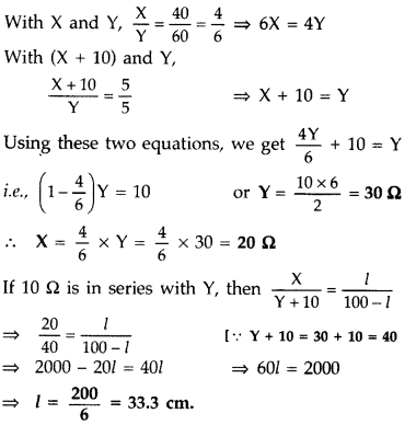
The figure shows experimental set up of a meter bridge. When the two unknown resistances X and Y are inserted, the null point D is obtained 40 cm from the end A. When a resistance of 10 Ω is connected in series with X, the null point shifts by 10 cm.
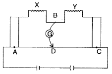
Find the position of the null point when the 10 Ω resistance is instead connected in series with resistance ‘Y’. Determine the values of the resistances X and Y. (Delhi 2008)
Answer:
Question 77.
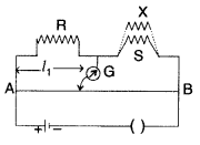
(i) State the principle of working of a meter bridge. x
(ii) In a meter bridge balance point is found at a distance l
1
with resistances R and S as shown in the figure.
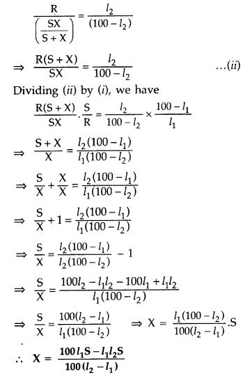
When an unknown resistance X is connected in parallel with the resistance S, the balance point shifts to a distance l
2
. Find the expression for X in terms of l
1
l
2
and S. (All India 2009)
Answer:
(i) Meter bridge : Meter bridge is an arrangement of four resistances used for measuring one unknown resistance in terms of other three known resistances.
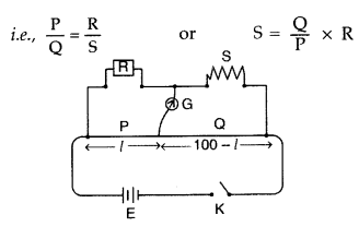
At the balance condition, no current flows through the galvanometer arm. By using the balance condition of meter bridge, the value of unknown resistance can be determined, knowing the other three resistances.
(ii) With R and S alone, we have
![]()
With S and X in parallel and R on the left gap
Question 78.
Write the principle of working of a potentiometer. Describe briefly, with the help of a circuit diagram, how a potentiometer is used to determine the internal resistance of a given cell. (Delhi 2009)
Answer:
Potentiometer : A potentiometer is a device used to measure potential difference.

Principle : The basic principle of a potentiometer is that when a constant current flows through a wire of uniform cross-sectional area and composition, the potential drop across any length of the wire is directly proportional to that length.
![]()
…where [K is called potential gradient
Close the key K
1
. A constant current flows through the potentiometer wire. With key K
2
kept open, move the jockey along AB till it balances the emf e of the cell. Let l, be the balancing length of the wire. If K is the potential gradient, then emf of the cell will be

![]()
With the help of resistance box R.B, introduce a resistance R and close key K
2
. Find the balance point for the terminal potential difference V of the cell. If l
2
is the balancing length, then

Let r be the internal resistance of the cell ε = I (R + r) and V = IR

Question 79.
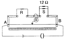
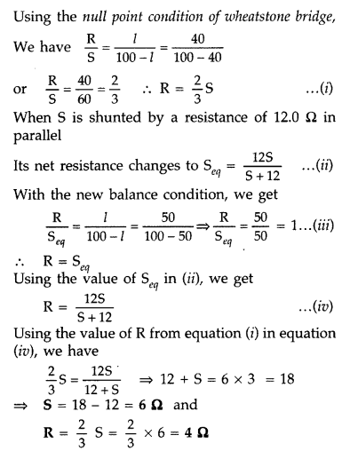
In a meter bridge, the null point is found at a distance of 40 cm from A. If a resistance of 12 Ω is connected in parallel with S, the null point occurs at 50.0 cm from A. Determine the values of R and S ?
Answer:
Answer:
Since the wire is of uniform cross-section, the resistances of the two segments of the wire AD and DB are in the ratio of the lengths of AD and DB.
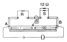
Using the null point condition of wheatstone bridge,
Question 80.
In a meter bridge, the null point is found at a distance of 60.0 cm from A.
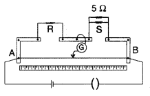
If now a resistance of 5 Q is connected in series with S, the null point occurs at 50 cm. Determine the values of R and S. (Delhi 2010)
Answer:
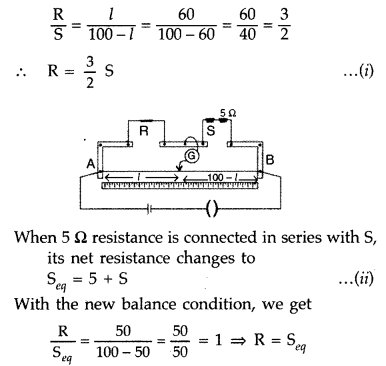
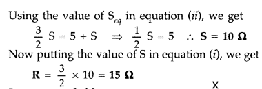
Using the null point condition of wheatstone bridge, we have
Question 81.
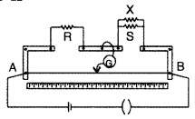
In a meter bridge, the null point is found at a distance of l
1
cm from A. If now a resistance of X is connected in parallel with S, the null point occurs at l
2
. Obtain a formula for X in terms of l
1
l
2
and S. (Delhi 2010)
Answer:
(i) Meter bridge : Meter bridge is an arrangement of four resistances used for measuring one unknown resistance in terms of other three known resistances.

At the balance condition, no current flows through the galvanometer arm. By using the balance condition of meter bridge, the value of unknown resistance can be determined, knowing the other three resistances.
(ii) With R and S alone, we have
![]()
With S and X in parallel and R on the left gap

Question 82.
Write any two factors on which internal resistance of a cell depends. The reading on a high resistance voltmeter, when a cell is connected across it, is 2.2 V. When the terminals of the cell are also connected to a resistance of 5 Ω as shown in the circuit, the voltmeter reading drops to 1.8 V. Find the internal resistance of the cell. (All India 2010)
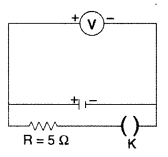
Answer:
(a) Internal resistance of a cell depends upon :
(i) nature of electrolyte of the cell
(ii) separation between the electrodes.
(b) Given: emf of cell, e = 2.2 V, R = 5 Ω, V = 1.8 V
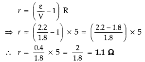
Question 83.
Write any two factors on which internal resistance of a cell depends. The reading on a high resistance voltmeter, when a cell is connected across it, is 2.0 V.
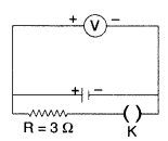
When the terminals of the cell are also connected to a resistance of 3Ω as shown in the circuit, the voltmeter reading drops to 1.5 V. Find the internal resistance of the cell. (All India 2010)
Answer:
Factors affecting internal resistance of a cell :
(a) Internal resistance of a cell depends upon :
(i) nature of electrolyte of the cell
(ii) separation between the electrodes.
(b) Given: emf of cell, e = 2.2 V, R = 5 Ω, V = 1.8 V

Let r be the internal resistance of the cell

Question 84.
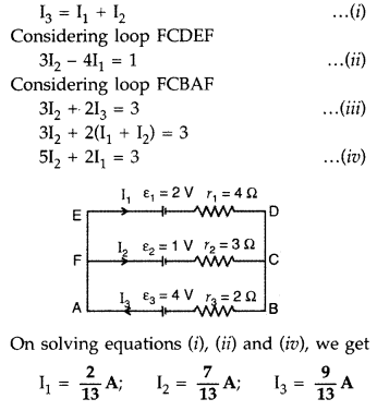
State Kirchhoff’s rules. Use these rules to write the expressions for the current I
1
I
2
and I
3
in the circuit diagram shown. (All India 2010)
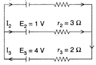
Answer:
(i) Kirchhoff’s junction rule : At any junction, the sum of the currents entering the junction is equal to the sum of currents leaving the junction.
(ii) Kirchhoff’s loop rule : The algebraic sum of changes in potential-in any closed loop involving resistors and cells is zero.
(b) According to Kirchhoff’s junction rule,
Question 85.
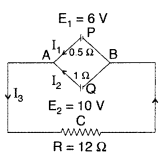
State Kirchhoff’s rules. Apply Kirchhoff’s rales to the loops ACBPA and ACBQA to write the expressions for the currents I
1
, I
2
and I
3
in the network. (All India 2010)
Answer:
Kirchhoff’s rules :
(i) Kirchhoff’s junction rule : At any junction, the sum of the currents entering the junction is equal to the sum of currents leaving the junction.
(ii) Kirchhoff’s loop rule : The algebraic sum of changes in potential-in any closed loop involving resistors and cells is zero.
(b) According to Kirchhoff’s junction rule,

Numerical : Applying Kirchhoff’s rule in loop ACBPA, we have
![]()
In loop ACBQA, by Kirchhoff’s rule, we have
12I
3
+ 1I
2
= 10 …(ii)
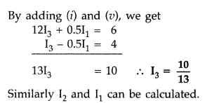
Subtracting (i) from (ii), we have

Question 87.
Define the terms
(i) drift velocity,
(ii) relaxation time.
A conductor of length L is connected to a dc source of emf e. If this conductor is replaced by another conductor of same material and same area of cross-section but of length 3L, how will the drift velocity change? (Delhi 2010)
Answer:
(i) Drift velocity : It may be defined as the average velocity gained by the free electrons of a conductor in the opposite direction of the externally applied field.
(ii) Relaxation time : The average time that elapses between two successive collisions of an electron is called relaxation time.
![]()
When length is tripled (3L), drift velocity becomes one-third of the original.
For details :
(i) Drift velocity. Drift velocity is defined as the velocity of the free electrons with which they get drifted towards the positive terminal under the influence of the external electric field. The drift velocity of electron is of the order of 10~5 m/ sec.
Derivation. Let ‘m’ be the mass of an electron and ‘e’ be the charge on it. When an external electric field ‘E is applied, the acceleration
acquired by an electron is given by
![]()
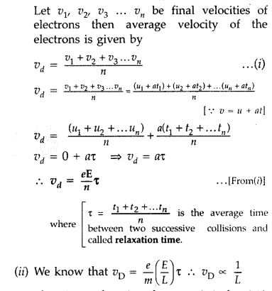
Let v
1
v
2
, v
3
… v
n
be final velocities of electrons then average velocity of the electrons is given by
Therefore, when length is tripled, the drift velocity becomes one-third.
Question 88.
In the circuit shown, R
1
= 4Ω, R
2
= R
3
= 15 Ω, R
4
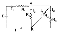
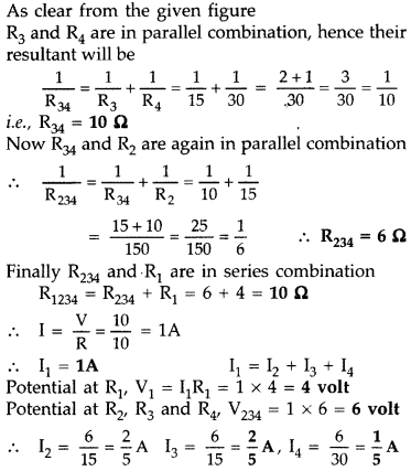
= 30Ω and E = 10V. Calculate the equivalent resistance of the circuit and the current in each resistor. (Delhi 2010)
Answer:
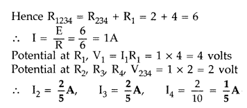
Question 89.
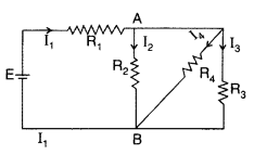
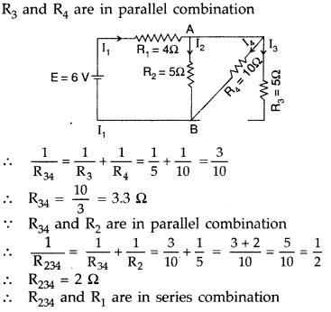
In the circuit shown, R1 = 4Ω, R2 = R3 = 5Ω, R4 = 10Ω and E = 6V. Work out the equivalent resistance of the circuit and the current in each resistor. (Delhi 2010)
Answer:
Question 90.
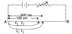
In the figure a long uniform potentiometer wire AB is having a constant potential gradient along its length. The null points for the two primary cells of emfs ε
1
and ε
2
connected in the manner shown are obtained at a distance of 120 cm and 300 cm from the end A.
Find (i) ε
1
/ε
2
(ii) position of null point for the cell ε
1
How is the sensitivity of a potentiometer increased ?
Answer:
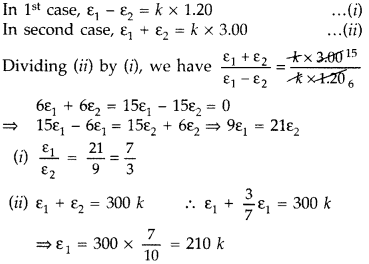
∴ Balancing length for cell ε
1
= 210 cm
The sensitivity of a potentiometer can be increased by reducing the potential gradient.
Question 91.
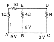
Using Kirchoff’s rules determine the value of unknown resistance R into circuit so that no current flows through 4ω resistance. Also find the potential difference between A and D. (Delhi 2012)
Answer:
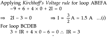
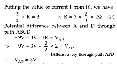
Question 92.
Calculate the value of the resistance R in the circuit shown in the figure so that the current in the circuit is 0.2 A. What would be the potential difference between points B and E? (All India 2012)
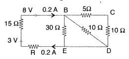
Answer:
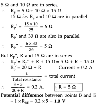
Question 93.
Calculate the value of the resistance R in the circuit shown in the figure so that the current is 0.2 A. What would be the potential difference between points A and B?
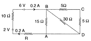
Answer:

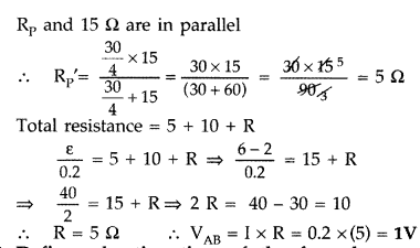
Question 94.
Define relaxation time of the free electrons drifting in a conductor. How is it related to the drift velocity of free electrons? Use this relation to deduce the expression for the electrical resistivity of the material. (All India 2012)
Answer:
Relaxation time : The average time that elapses between two successive collisions of an electron is called relaxation time.

Suppose a potential difference V is applied across a conductor of length T and of uniform cross-section A, then
Electric field E set up inside the conductor is given by
![]()
Under the influence of field \(\overrightarrow{\mathrm{E}}\), the free electrons begin to drift in the opposite direction \(\overrightarrow{\mathrm{E}}\) with an average drift velocity v
d
.
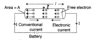
Let the number of electrons per unit volume or electron density = n
Charge on an electron = e
Number of electrons in length l of the conductor = n × volume of the conductor = nAl
Total charge contained in length l of the conductor, q = enAl
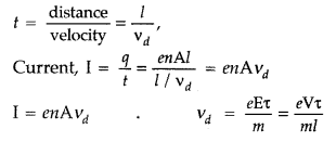
According to the electrons which enter the conductor at the right end will pass through the conductor at the left end in time,
Question 95.
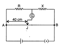
Write the principle on which the working of a meter bridge is based. In an experiment on meter bridge, a student obtains the balance point at the point J such that AJ = 40 cm as shown in the figure. The values of ‘R’ and ‘X’ are both doubled and then interchanged. Find the new position of the balance point. If the galvanometer and battery are also interchanged, how will the position of balance point be affected? (Comptt. All India 2012)
Answer:
The principle on which the working of a meter bridge is based, is Wheatstone bridge.
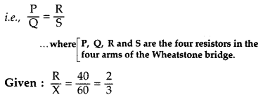
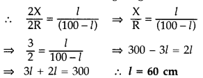
When R and X are doubled and interchanged Let the new balancing length be l.
If the galvanometer and battery are also inter¬changed then there will be no effect on the posi¬tion of the balance point.
Question 96.
Write the principle on which the working of a meter bridge is based. In an experiment on meter bridge, a student obtains the balance point at the point J such that AJ = 60 cm as shown in the figure. The values of ‘R’ and ‘X’ are both doubled and then interchanged. Find the new position of the balance point. If the galvanometer and battery are also interchanged, how will the position of balance point be affected? (Comptt. All India 2012)
Answer:
The principle on which the working of a meter bridge is based, is Wheatstone bridge.
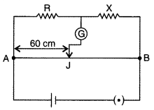
If the galvanometer and battery are interchanged, then there will be no effect on the position of balancing point.
Question 97.
Define the current sensitivity of galvanometer. Write its S.I. unit.
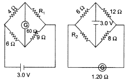
Figure shows two circuits each having a galvanometer and a battery of 3 V.
When the galvanometers in each arrangment do not show any deflection, obtain the ratio R
1
/R
2
.
(All India 2012)
Answer:
Current sensitivity of a galvanometer : Current sensitivity of a moving coil galvanometer is defined as deflection produced in the galvanometer per unit current passed through it. Its SI unit is rad A
-1
(i) For circuit on the left side—
If G has zero deflection, then

(ii) For circuit on the right side—
If galvanometer and battery are inter-changed, there is no change in the circuit as such.

Question 98.
State the underlying principle of a potentiometer. Write two factors on which the sensitivity of a potentiometer depends.
In the potentiometer circuit shown in the figure, the balance point is at X. State, giving reason, how the balance point is shifted when
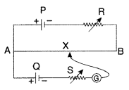
(i) resistance R is increased?
(ii) resistance S is increased, keeping R constant? (Comptt. Delhi 2012)
Answer:
Potentiometer : A potentiometer is a device used to measure potential difference.

Principle. When a current flows through a wire of uniform thickness, the potential difference be¬tween its two points is directly proportional to the length of the wire between these two points.
![]()
… when [K is called construction potential gradient]
Two factors :
(a) Potential gradient
(b) Length of potentiometer wire.
(i) When R is increased, the balance point will shift towards B.
(ii) If resistance S increased keeping ‘R’ constant, the balance points will not change.
Question 99.
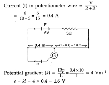
A potentiometer wire of length 1 m has a resistance of 10 Ω. It is connected to a 6 V battery in series with a resistance of 5 Ω. Determine the emf of the primary cell which gives a balance point at 40 cm. (Delhi 2012)
Answer:
Length (l) = 1 m
Resistance of potentiometer wire = 10Ω
Question 100.
A potentiometer wire of length 1.0 m has a resistance of 15 Ω. It is connected to a 5 V battery in series with a resistance of 5 Ω. Determine the emf of the primary cell which gives a balance point at 60 cm. (Delhi 2012)
Answer:
Length (l) = 1 m
Resistance of potentiometer wire = 10Ω

Question 101.
A potentiometer wire of length 1 m has a resistance of 5 Ω. It is connected to a 8 V battery in series with a resistance of 15 Ω. Determine the emf of the primary cell which gives a balance point at 60 cm. (Delhi 2012)
Answer:
Length (l) = 1 m
Resistance of potentiometer wire = 10Ω

Question 102.
Answer the following :
(a) Why are the connections between the resistors in a meter bridge made of thick copper strips?
(b) Why is it generally preferred to obtain the balance point in the middle of the meter bridge wire?
(c) Which material is used for the meter bridge wire and why? (All India 2012)
Answer:
(a) The connections between the resistors in a meter bridge are made of thick copper strip, so as to have the minimum possible resistances.
(b) It is generally preferred to obtain the balance point in the middle of the meter bridge, so as to minimise the error of balance.
(c) The material used for meter bridge is an alloy ‘constantant’ or ‘manganin’ because of
(i) hight resistivity and
(ii) low temperature coefficient of resistivity.
Question 103.
A resistance of R Ω draws current from a potentiometer shown in the figure.
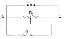
The potentiometer has a total resistance R
0
Ω. A voltage V is supplied to the potentiometer. Derive an expression for the voltage across R when the sliding contact is in the middle of the potentiometer.
Answer:
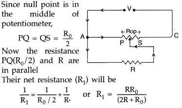
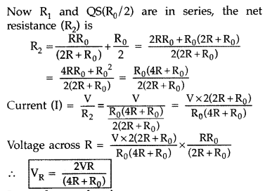
Question 104.
In the electric network shown in the figure, use Kirchhoffs rules to calculate the power consumed by the resistance R = 4 Ω. (Comptt. Delhi 2012)
Answer:
-12 + 2I
1
+ 4(I
1
+ I
2
) = 0
-12 + 2I
1
+ 4 I
1
+ 4I
2
= 0
6I
1
+ 4I
2
= 12 ⇒ 3I
1
+ 2I
2
= 6 … (i)
For loop ADFEA
-4(I
1
+ I
2
) + 6 = 0
-4I
1
– 4I
2
= -6 ⇒ 2I
1
+ 2I
2
= 3 … (ii)
Solving (i) and (ii), we get
I
1
= 3A and I
2
= -1.5A
∴ Power consumed in 4Ω resistance (R) = I
2
R
= (I
1
+ I
2
)
2
× R
= (3 – 1.5)
2
× 4 W
= 9 watt
Question 105.
In the electric network shown in the figure use Kirchhoffs rules to calculate the power consumed by the resistance R = 8 Ω. (Comptt. Delhi 2012)
Answer:
In loop BCDA,
I
1
× 4 + (I
1
+ I
2
) × 8 = 12
4I
1
+ 8I
1
+ 8I
2
= 12
12I
1
+ 8I
2
= 12
∴ 3I
1
+ 2I
2
= 3 … (Dividing by 4) … (i)
In loop ADFE,
(I
1
+ I
2
) × 8 = 8 => 8I
1
, + 8I
2
= 8
∴ I
1
+ I
2
= 1 …(Dividing by 8)
Solving equations (i) and (ii), we get
I
1
= 1A and I
2
= 0A
∴ Power consumed in 80 resistance (R) = I
2
R
= (I
1
+ I
2
)
2
× R
= (1 + 0)
2
× 8 = 8 watt
Question 106.
(a) State the underlying principle of a potentiometer. Why is it necessary to
(i) use a long wire,
(ii) have uniform area of cross-section of the wire and
(iii) use a driving cell whose emf is taken to be greater than the emfs of the primary cells?
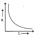
(b) In a potentiometer experiment, if the area of the cross-section of the wire increases uniformly from one end to the other, draw a graph showing how potential gradient would vary as the length of the wire increases from one end.(Comptt. All India 2012)
Answer:
(a) Principle of potentiometer: A potentiometer is a device used to measure potential difference.

Principle. When a current flows through a wire of uniform thickness, the potential difference between its two points is directly proportional to the length of the wire between these two points.
![]()
… when [K is called construction potential gradient]
Reasons :
(i) We use a long wire to have a lower value of potential gradient (i.e. a lower ‘least count’ or greater sensitivity of the potentiometer).
(ii) The area of cross section has to be uniform to get a ‘uniform wire’ as per the principle of the potentiometer to ensure a constant value of resistance per unit length of the wire.
(iii) The emf of the driving cell has to be greater than the emf of the primary cells as otherwise no balance point would be obtained.
(b) Potential gradient K = \(\frac{\mathrm{V}}{\mathrm{L}}\)
Therefore the required graph is as shown here.
Question 107.
A cell of emf ‘E’ and internal resistance V is connected across a variable load resistor R. Draw the plots of the terminal voltage V versus
(i) R and
(ii) the current I.
It is found that when R = 4 Ω, the current is 1 A and when R is increased to 9 Ω, the current reduces to 0.5 A. Find the values of the emf E and internal resistance r. (Delhi 2012)
Answer:
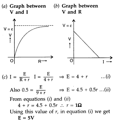
Question 108.
State the principle of working of a galvanometer.
A galvanometer of resistance G is converted into a voltmeter to measure upto V volts by connecting a resistance Rx in series with the coil. If a resistance R
2
is connected in series with it, then it can measure upto V/2 volts. Find the resistance, in terms of R
1
and R
2
, required to be connected to convert it into a voltmeter that can read upto 2V. Also find the resistance G of the galvanometer in terms of R
1
and R
2
. (Delhi 2012)
Answer:
(a) Working principle of galvanometer :
A current carrying coil experiences a torque when placed in a magnetic field which tends to rotate the coil and produces an angular defletion.
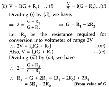
Question 109.
Find the relation between drift velocity and relaxation time of charge carriers in a conductor. A conductor of length L is connected to a d,c. source of emf ‘E’. If the length of the conductor is tripled by stretching it, keeping ‘E’ constant, explain how its drift velocity would be affected. (All India 2012)
Answer:
(i) Drift velocity. Drift velocity is defined as the velocity of the free electrons with which they get drifted towards the positive terminal under the influence of the external electric field. The drift velocity of electron is of the order of 10
-5
m/ sec.
Derivation. Let ‘m’ be the mass of an electron and ‘e’ be the charge on it. When an external electric field ‘E is applied, the acceleration
acquired by an electron is given by
![]()
Let v
1
v
2
, v
3
… v
n
be final velocities of electrons then average velocity of the electrons is given by

Therefore, when length is tripled, the drift velocity becomes one-third.
Question 110.
In the two electric circuits shown in the figure, determine the reading of ideal ammeter (A) and the ideal voltmeter (V). (Comptt. Delhi 2012)
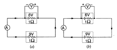
Answer:
(i) In circuit (a)
Total emf = 15 V, Total Resistance = 2Ω

Potential difference between the terminals of 6 V battery
V = E – iR = [6 – (7.5 × 1) = -1.5 V
(ii) In circuit (b)
Effective emf = (9 – 6)V = 3V,
Total Resitance = 2Ω

Potential Difference across 6 V cell,
V = E – (- I)R = V + IR
(∵ Current is in opposite direction to 6 V cell)
= 6 + 1.5 × 1 = 7.5 V
Question 111.
In the circuit shown in the figure, find the current through each resistor. (Comptt. Delhi 2012)
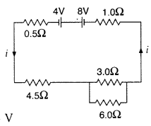
Answer:
Total emf of the circuit
=8V – 4V = 4V
Since two resistors 30 and 60 are connected in parallel, their combined resistance is
![]()
Since all resistors are in series,
R = 0.5 + 4.5 + 2 + 1 = 8Ω
![]()
0.5Ω A current will flow in 3 resistors, i.e., 0.5Ω, 4.5Ω and 1Ω.
Current through resistors 30 and 60

Question 112.
(a) Deduce the relation between current I flowing through a conductor and drift velocity \(\overrightarrow{\mathbf{v}}_{d}\) of the electrons.
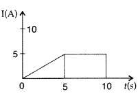
(b) Figure shows a plot of current ‘I’ flowing through the cross-section 5 of a wire versus the time ‘t’. Use the plot to find the charge flowing in 10s through the wire.
 (Comptt. All India 2012)
Answer:
(a) Relation between electric current and drift velocity : Consider a uniform metallic wire XY of length l and cross-sectional area A. A potential difference V is applied across the ends X and Y of the wire. This causes an electric field at each point of the wire of strength :
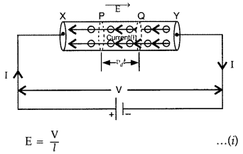
Due to this electric field, the electrons gain a drift velocity V
d
opposite to direction of electric field. If q be the charge passing through the cross-section of wire in t seconds, then, current in wire, I = \(\frac{q}{t}\)
The distance transversed by each electron in time (t) = drift velocity × time = V d t
If we consider two planes P and Q at a distance V d t in a conductor, then the total charge flowing in time t will be equal to the total charge on the electrons present within the cylinder PQ.
The volume of this cylinder = cross sectional area × length = A V d t
If n is the number of free electrons in the wire per unit volume, then the number of free electrons in the cylinder = n(A V
d
t)
If charge on each electron is -e (e = 1.6 × 10
-19
C), then the total charge flowing through a cross-section of the wire,

This is the relation between electric current and drift velocity. Negative sign shows that the direction of current is opposite to the drift velocity.
(b) Charge = Current × time
(i) For 0 to 5 seconds, the current
![]()
Hence, q
1
= (2.5) × (5) = 12.5 C
(ii) For 5 sec to 10 sec, the current = 5A
Hence, q
2
= 5 × (10 – 5) = 5 × 5 = 25 C
q = q
1
+ q
2
= 12.5 + 25 = 37.5 C
Question 113.
Draw a circuit diagram of a potentiometer. State its working principle. Derive the necessary formula to describe how it is used to compare the emfs of the two cells. (Comptt. All India)
Answer:
(a) Principle : The basic principle of a potentiometer is that “when a constant current flows through a wire of uniform cross-sectional area and composition, the potential drop across any length of the wire is directly proportional to that length.
\(v \propto l\)
Comparison of emf’s of two cells: First of all the ends of potentiometer are connected to a battery Bx,
key K and rheostat Rh such that the positive terminal of battery B, is connected to end A of the wire. This completes the primary circuit.
Now the positive terminals of the cells C 1 and C 2 whose emfs are to be compared are connected to A and the negative terminals to the jockey J through a two-way key and a galvanometer (fig). This is the secondary circuit.
Method:
(i) By closing key K, a potential difference is established and rheostat is so adjusted that when jockey J’is made to touch at ends A and B of wire, the deflection in galvano¬meter is on both sides. Suppose in this position the potential gradient is k.
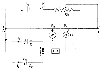
(ii) Now plug is inserted between the terminals 1 and 3. so that cell C
1
is included in the secondary circuit and jockey J is slided on the wire at P
1
(say) to obtain the null point. The distance of P
1
from A is measured. Suppose this length is l
1
, i.e. AP
1
= l
1
![]()
(iii) Now plug is taken off between the terminals 1 and 3 and inserted in between the terminals 2 and 3 to bring cell C
2
in the circuit. Jockey is slided on wire and null deflection position P
2
is noted. Suppose distance of P
2
from A is l
2
i.e. AP
2
= Z
2
The emf of cell C
2
, e
2
= kl
2
… (ii)
![]()
Thus emf’s of cells may be compared. Out of these cells if one is standard cell, then the emf of other cell may be calculated.
(b) Causes for one sided deflection :
(i) Potential difference between the ends of the potentiometer wire is less than the emf of the cell in the secondary circuit.
(ii) The positive side of the driving cell is connected to the negative terminal of the cell in the secondary circuit.
Question 114.
With the help of the circuit diagram, explain the working principle of meter bridge. How is it used to determine the unknown resistance of a given wire? Write the necessary precautions to minimize the error in the result. (Comptt. All India 2012)
Answer:
Metre Bridge is special case of Wheatstone Bridge
It is a device based on Wheatstone bridge to determine the unknown resistance of a wire. Principle : Meter bridge is based on the principle of wheatstone bridge, i.e. when bridge is balanced

Circuit : To find the unknown resistance S, the circuit is completed as shown in figure. The unknown resistance wire of resistance S is connected across the gap between points C and D and a resistance box (R) is connected across the gap between the points A and D. A cell, a rheostat and a key (K) is connected between the point A and C by means of connecting screws. In the experiment when the sliding jockey touches the wire AC at any point, then the wire is divided into two parts. These two parts AB and BC act as the resistances P and Q of the Wheatstone bridge. In this way the resistances of arms AB, BC, AD and DC form the resistances P, Q, R and S of Wheatstone bridge. Thus the circuit of meter bridge is the same as that of Wheatstone bridge.
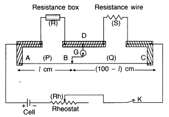
Method : To determine the unknown resistance first of all key K is closed and a resistance R is taken in the resistance box in such a way that on pressing jockey B at end points A and C, the deflection in galvanometer is on both the sides. Now jockey is slided on wire at such a position that on pressing the jockey on the wire at that point, there is no deflection in the galvanometer G. In this position the points B and D are at the same potential, therefore the bridge is balanced. The point B is called the null point. The length of both parts AB and BC of the wire are read on the scale. The condition of balance of Wheatstone bridge is,

If r is the resistance per cm length of wire AC and l cm is the length of wire AB, then length of wire BC will be (100 – l) cm
∴ P = resistance of wire AB = lr
Q = resistance of wire BC = (100 – l)r
Substituting these values in equation (i), we get
![]()
As the resistance (R) of wire (AB) is known, the resistance S may be calculated.
A number of observations are taken for different resistances taken in resistance box and S is calculated each time and the mean value of S is found.
Precautions:
(i) In this experiment the resistance of the copper strips and connecting screws have not been taken into account. These resistances are called end-resistances. Therefore very small resistances cannot be found accurately by metre bridge. The resistance S should not be very small.
(ii) The current should not flow in the metre bridge wire for a long time, otherwise the wire will become hot and its resistance will be changed.
Question 115.
(i) Derive an expression for drift velocity of free electrons.
(ii) How does drift velocity of electrons in a metallic conductor vary with increase in temperature? Explain. (All India)
Answer:
(i) Expression for drift velocity : When a potential difference is applied across a conductor, an electric field is produced and free electrons are acted upon by an electric force (= -Ee). Due to this, electrons accelerate and keep colliding with each other and acquire a constant (average) velocity v
d

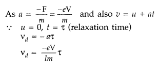
(ii) The drift velocity of electrons decreases with temperature, because the time of relaxation decreases.
Question 116.
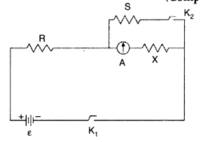
The reading of the (ideal) ammeter, in the circuit shown here, equals :
(i) I when key K
1
is closed but key K
2
is open.
(ii) \(\frac{\mathbf{I}}{2}\) when both keys K
1
and K
2
are closed.
Find the expression for the resistance of X in terms of the resistances of R and S. (Comptt. Delhi 2012)
Answer:
Finding the expression for the resistance X
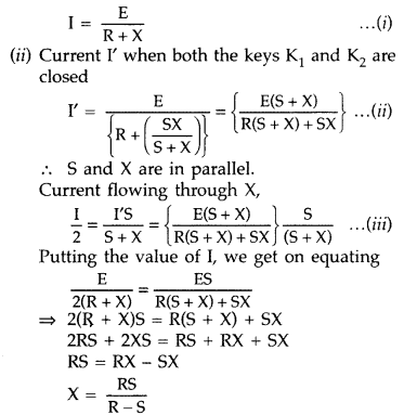
(i) Current I when K2 is open and Kj is closed E
Question 117.
The temperature coefficient of resistivity, for two materials A and B, are 0.0031/°C and 0.0068/ °C, respectively.
Two resistors, R
1
and R
2
made from materials A and B, respectively, have resistances of 200Ω and 100Ω at 0°C. Show on a diagram, the ‘colour code’, of a carbon resistor, that would have a resistance equal to the series combination of R
1
and R
2
, at a temperature of 100°C.
(Neglect the ring corresponding to the tolerance of the carbon resistor) (comptt. Delhi 2012)
Answer:
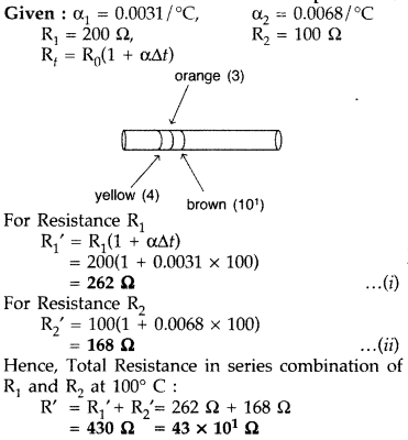
Question 118.
A student connects a cell, of emf E
2
and internal resistance r
2
with a cell of emf E
1
and internal resistance r
1
, such that their combination has a net internal combination resistance R.
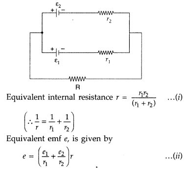
Draw a diagram of the ‘set-up’ and obtain an expression for the current flowing through the resistance R. (Comptt. Outside Delhi 2016)
Answer:
Since the net internal resistance of two cells is less than r
1
it means that the two cells must have been
connected in parallel
The diagram of the setup is as shown

Question 119.
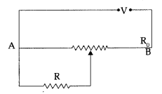
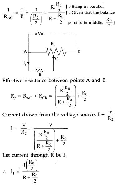
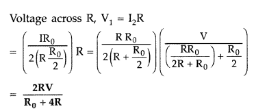
A resistance of R draws current from a potentiometer. The potentiometer wire, AB, has a total resistance of R0. A voltage V is supplied to the potentiometer. Derive an expression for the voltage across R when the sliding contact is in the middle of potentiometer wire. (Delhi 2016)
Answer:
Given : Total resistance of potentiometer wire AB = R
0
Voltage applied = V,
Given resistance = R Resistance between points A and C
Question 120.
(a) The potential difference applied across a given resistor is altered so that the heat produced per second increases by a factor of 9. By what factor does the applied potential difference change?
(b) In the figure shown, an ammeter A and a resistor of 40 are connected to the terminals of the source. The emf of the source is 12 V having an internal resistance of 2 O. Calculate the voltmeter and ammeter readings. (Outside Delhi 2017)
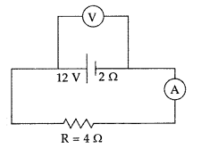
Answer:
(a) Heat produced in a resistor ‘R’ when applied, potential difference V, is :
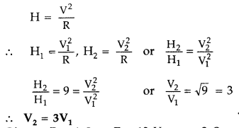
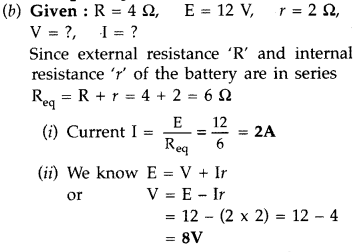
Question 121.
(a) write the principle of working of a metre bridge.
(b) In a metre bridge, the balance point is found at a distance l
1
with resistances R and S as shown in the figure.
An unknown resistance X is now connected in parallel to the resistance S and the balance point is found at a distance l
2
. Obtain a formula for X in terms of l
1
, l
2
and S. (Outside Delhi 2017)
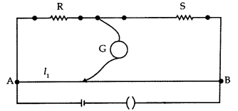
An unknown resistance X is now connected in parallel to the resistance S and the balance point is found at a distance l
2
. Obtain a formula for X in terms of l
1
l
2
and S. (Outside Delhi) R
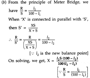
Answer:
Metre Bridge is special case of Wheatstone Bridge
It is a device based on Wheatstone bridge to determine the unknown resistance of a wire.
Principle : Meter bridge is based on the principle of wheatstone bridge, i.e. when bridge is balanced

Circuit : To find the unknown resistance S, the circuit is completed as shown in figure. The unknown resistance wire of resistance S is connected across the gap between points C and D and a resistance box (R) is connected across the gap between the points A and D. A cell, a rheostat and a key (K) is connected between the point A and C by means of connecting screws. In the experiment when the sliding jockey touches the wire AC at any point, then the wire is divided into two parts. These two parts AB and BC act as the resistances P and Q of the Wheatstone bridge. In this way the resistances of arms AB, BC, AD and DC form the resistances P, Q, R and S of Wheatstone bridge. Thus the circuit of meter bridge is the same as that of Wheatstone bridge.

Method : To determine the unknown resistance first of all key K is closed and a resistance R is taken in the resistance box in such a way that on pressing jockey B at end points A and C, the deflection in galvanometer is on both the sides. Now jockey is slided on wire at such a position that on pressing the jockey on the wire at that point, there is no deflection in the galvanometer G. In this position the points B and D are at the same potential, therefore the bridge is balanced. The point B is called the null point. The length of both parts AB and BC of the wire are read on the scale. The condition of balance of Wheatstone bridge is,

If r is the resistance per cm length of wire AC and l cm is the length of wire AB, then length of wire BC will be (100 – l) cm
∴ P = resistance of wire AB = lr
Q = resistance of wire BC = (100 – l)r
Substituting these values in equation (i), we get
![]()
As the resistance (R) of wire (AB) is known, the resistance S may be calculated.
A number of observations are taken for different resistances taken in resistance box and S is calculated each time and the mean value of S is found.
Precautions:
(i) In this experiment the resistance of the copper strips and connecting screws have not been taken into account. These resistances are called end-resistances. Therefore very small resistances cannot be found accurately by metre bridge. The resistance S should not be very small.
(ii) The current should not flow in the metre bridge wire for a long time, otherwise the wire will become hot and its resistance will be changed.
Question 122.
Derive the expression for the current density of a conductor in terms of the conductivity and applied electric field. Explain, with reason how the mobility of electrons in a conductor changes when the potential difference applied is doubled, keeping the temperature of the conductor constant. (Comptt. Delhi 2017)
Answer:
(i) Derivation of expression for current density—
Using Ohm’s law,
![]()
Potential difference (V), across the ends of a conductor of length ‘l’ where field ‘E’ is applied, is given by
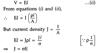

So, as potential is doubled, drift velocity also gets doubled, therefore, there will be no change in mobility.
Question 123.
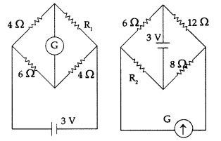
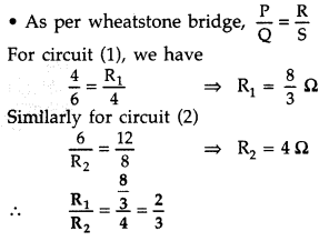
Define the term current sensitivity of a galvanotmer. In the circuits shown in the figures, the galvanometer shows no deflection in each case. Find the ratio of R
1
and R
2
. (Comptt. All India 2017)
Answer:
Current Electricity Class 12 Important Questions Long Answer Type
Question 124.
(a) Derive the relation between current density ‘\(\overrightarrow{\mathbf{J}}\)‘ and potential difference ‘V’ across a current carrying conductor of length area of cross-section ‘A’ and the number density of free electrons.
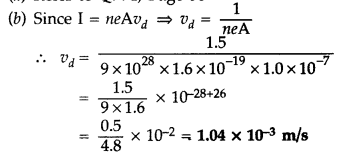
(b) Estimate the average drift speed of conduc¬tion electrons in a copper wire of cross-sectional area 1.0 × 10
-7
m
2
carrying a current of 1.5 A. [Assume that the number density of conduction electrons is 9 × 10
28
m
-3
] (Comptt. Delhi 2012)
(a)
Suppose a potential difference V is applied across a conductor of length l and of uniform cross-section A. The electric field E set up inside the conductor is given by
E = \(\frac{V}{l}\)
Under the influence of field \(\overrightarrow{\mathrm{E}}\), the free electrons begin to drift in the opposite direction \(\overrightarrow{\mathrm{E}}\) with an average drift velocity v
d
.
Let the number of electrons per unit volume or electron density = n
Charge on an electron = e

No. of electrons in length l of the conductor = n x volume of the conductor = n × Al
Total charge contained in length l of the conductor is
q = enAl … (i)
All the electrons which enter the conductor at the right end will pass through the conductor at the left end in time,

Hence the current density of a metallic conductor is directly proportional to the drift speed of electrons.
Question 125.
Use Kirchhoff’s rules to obtain the balance condition in a Wheatstone bridge.
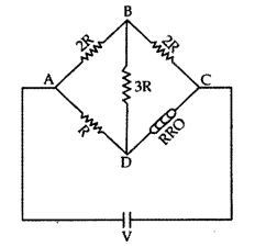
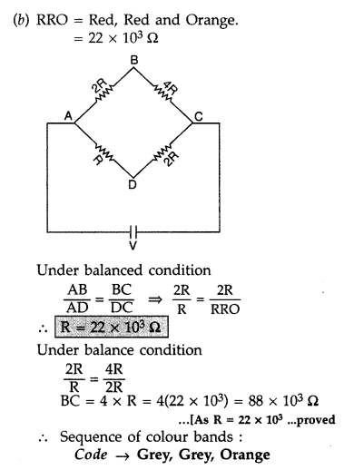
Calculate the value of R in the balance condition of the Wheatstone bridge, if the carbon resistor connected across the arm CD has the colour sequence red, red and orange, as is shown in the figure.
If now the resistances of the arms BC and CD are interchanged, to obtain the balance condition, another carbon resistor is connected in place of R. What would now be the sequence of colour bands of the carbon resistor? (Comptt. Delhi 2012)
Answer:
(a) Derivation of balance condition from Kirchhoff’s laws :
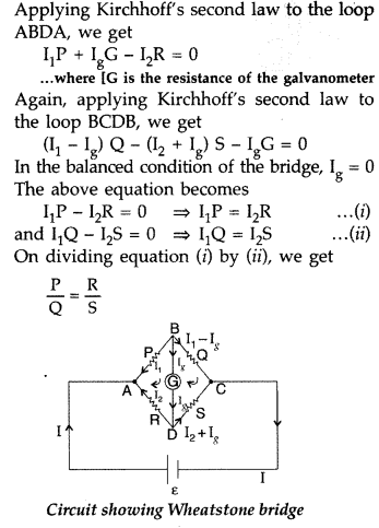
Thus this equation relating to the four resistors is called the balance condition for the galvanometer to give zero or null deflection.
Question 126.
(a) State the working principle of a potentiometer. With the help of the circuit diagram, explain how a potentiometer is used to compare the emf’s of two primary cells. Obtain the required expression used for comparing the emfs.
(b) Write two possible causes for one sided deflection in a potentiometer experiment. (Delhi 2012)
Answer:
(a) Principle : The basic principle of a potentiometer is that “when a constant current flows through a wire of uniform cross-sectional area and composition, the potential drop across any length of the wire is directly proportional to that length.
\(v \propto l\)
Comparison of emf’s of two cells: First of all the ends of potentiometer are connected to a battery Bx,
key K and rheostat Rh such that the positive terminal of battery B, is connected to end A of the wire. This completes the primary circuit.
Now the positive terminals of the cells C 1 and C 2 whose emfs are to be compared are connected to A and the negative terminals to the jockey J through a two-way key and a galvanometer (fig). This is the secondary circuit.
Method:
(i) By closing key K, a potential difference is established and rheostat is so adjusted that when jockey J’is made to touch at ends A and B of wire, the deflection in galvano¬meter is on both sides. Suppose in this position the potential gradient is k.

(ii) Now plug is inserted between the terminals 1 and 3. so that cell C
1
is included in the secondary circuit and jockey J is slided on the wire at P
1
(say) to obtain the null point. The distance of P
1
from A is measured. Suppose this length is l
1
, i.e. AP
1
= l
1
![]()
(iii) Now plug is taken off between the terminals 1 and 3 and inserted in between the terminals 2 and 3 to bring cell C
2
in the circuit. Jockey is slided on wire and null deflection position P
2
is noted. Suppose distance of P
2
from A is l
2
i.e. AP
2
= Z
2
The emf of cell C
2
, e
2
= kl
2
… (ii)
![]()
Thus emf’s of cells may be compared. Out of these cells if one is standard cell, then the emf of other cell may be calculated.
(b) Causes for one sided deflection :
(i) Potential difference between the ends of the potentiometer wire is less than the emf of the cell in the secondary circuit.
(ii) The positive side of the driving cell is connected to the negative terminal of the cell in the secondary circuit.
Question 127.
(a) State Kirchhoff’s rules for an electric network. Using Kirchhoff’s rules, obtain the . balance condition in terms of the resistances
of four arms of Wheatstone bridge.
(b) In the meterbridge experimental set up, shown in the figure, the null point ‘D’ is obtained at a distance of 40 cm from end A of the meterbridge wire. If a resistance of 10 Ω is connected in series with R
1
, null point is obtained at AD = 60 cm. Calculate the values of R
1
and R
2
(Delhi 2012)
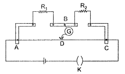
Answer:
(a) Kirchhoff’s Rules:
(i) Junction rule. At any junction of circuit elements, the algebraic sum of currents entering the junction must be equal to the sum of currents leaving it. i.e. ΣI = 1
(ii) Loop rule. The algebraic sum of changes in potential around any closed loop involving resistors and cells in the loop is zero.
![]()
Balance condition of wheatstone bridge :
(a) Derivation of balance condition from Kirchhoff’s laws :

Thus this equation relating to the four resistors is called the balance condition for the galvanometer to give zero or null deflection.

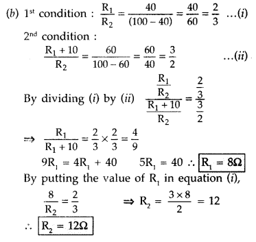
Question 128.
(i) Define the term drift velocity.
(ii) On the basis of electron drift, derive an expression for resistivity of a conductor in terms of number density of free electrons and relaxation time. On what factors does resistivity of a conductor depend?
(iii) Why alloys like constantan and manganin are used for making standard resistors? (Delhi 2017)
Answer:
(i) Drift velocity may be defined as the average velocity gained by the free electrons of a conductor in the opposite direction of the externally applied field.
(ii)
Relaxation time : The average time that elapses between two successive collisions of an electron is called relaxation time.

Suppose a potential difference V is applied across a conductor of length T and of uniform cross-section A, then
Electric field E set up inside the conductor is given by
![]()
Under the influence of field \(\overrightarrow{\mathrm{E}}\), the free electrons begin to drift in the opposite direction \(\overrightarrow{\mathrm{E}}\) with an average drift velocity v
d
.

Let the number of electrons per unit volume or electron density = n
Charge on an electron = e
Number of electrons in length l of the conductor = n × volume of the conductor = nAl
Total charge contained in length l of the conductor, q = enAl
According to the electrons which enter the conductor at the right end will pass through the conductor at the left end in time,


(iii) Because constantan and manganin show very weak dependence of resistivity on temperature. .
Question 129.
State the principle potentiometer.
(i) State the principle of working of a potentiometer
(ii) In the given potentiometer circuit AB is a uniform wire of length 1 m and resistance 10Ω. Calculate the potential gradient along the wire and balance length AO (= l). (Delhi 2017)
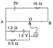
Answer:
(i)
(a) Principle : The basic principle of a potentiometer is that “when a constant current flows through a wire of uniform cross-sectional area and composition, the potential drop across any length of the wire is directly proportional to that length.
\(v \propto l\)
Comparison of emf’s of two cells: First of all the ends of potentiometer are connected to a battery Bx,
key K and rheostat Rh such that the positive terminal of battery B, is connected to end A of the wire. This completes the primary circuit.
Now the positive terminals of the cells C 1 and C 2 whose emfs are to be compared are connected to A and the negative terminals to the jockey J through a two-way key and a galvanometer (fig). This is the secondary circuit.
Method:
(i) By closing key K, a potential difference is established and rheostat is so adjusted that when jockey J’is made to touch at ends A and B of wire, the deflection in galvano¬meter is on both sides. Suppose in this position the potential gradient is k.

(ii) Now plug is inserted between the terminals 1 and 3. so that cell C
1
is included in the secondary circuit and jockey J is slided on the wire at P
1
(say) to obtain the null point. The distance of P
1
from A is measured. Suppose this length is l
1
, i.e. AP
1
= l
1
![]()
(iii) Now plug is taken off between the terminals 1 and 3 and inserted in between the terminals 2 and 3 to bring cell C
2
in the circuit. Jockey is slided on wire and null deflection position P
2
is noted. Suppose distance of P
2
from A is l
2
i.e. AP
2
= Z
2
The emf of cell C
2
, e
2
= kl
2
… (ii)
![]()
Thus emf’s of cells may be compared. Out of these cells if one is standard cell, then the emf of other cell may be calculated.
(b) Causes for one sided deflection :
(i) Potential difference between the ends of the potentiometer wire is less than the emf of the cell in the secondary circuit.
(ii) The positive side of the driving cell is connected to the negative terminal of the cell in the secondary circuit.
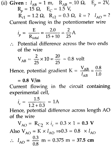
Question 130.
(a) Obtain the condition under which the current flowing, in the ‘current detecting device’, used in the circuit shown in the figure, becomes zero.
(b) Describe briefly the device, based on the above condition. Draw a circuit diagram for this device and discuss, in brief, how it is used for finding an unknown resistance. (Comptt All India 2016)
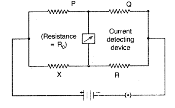
Answer:
(a) The given circuit can be redrawn as :
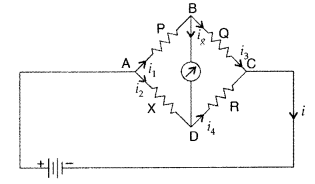
It is, therefore, a wheatstone bridge
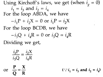
(b) A simple device, based on the above condition is ‘Meter Bridge’.
Working of Meter Bridge :
Metre Bridge is special case of Wheatstone Bridge
It is a device based on Wheatstone bridge to determine the unknown resistance of a wire. Principle : Meter bridge is based on the principle of wheatstone bridge, i.e. when bridge is balanced

Circuit : To find the unknown resistance S, the circuit is completed as shown in figure. The unknown resistance wire of resistance S is connected across the gap between points C and D and a resistance box (R) is connected across the gap between the points A and D. A cell, a rheostat and a key (K) is connected between the point A and C by means of connecting screws. In the experiment when the sliding jockey touches the wire AC at any point, then the wire is divided into two parts. These two parts AB and BC act as the resistances P and Q of the Wheatstone bridge. In this way the resistances of arms AB, BC, AD and DC form the resistances P, Q, R and S of Wheatstone bridge. Thus the circuit of meter bridge is the same as that of Wheatstone bridge.

Method : To determine the unknown resistance first of all key K is closed and a resistance R is taken in the resistance box in such a way that on pressing jockey B at end points A and C, the deflection in galvanometer is on both the sides. Now jockey is slided on wire at such a position that on pressing the jockey on the wire at that point, there is no deflection in the galvanometer G. In this position the points B and D are at the same potential, therefore the bridge is balanced. The point B is called the null point. The length of both parts AB and BC of the wire are read on the scale. The condition of balance of Wheatstone bridge is,

If r is the resistance per cm length of wire AC and l cm is the length of wire AB, then length of wire BC will be (100 – l) cm
∴ P = resistance of wire AB = lr
Q = resistance of wire BC = (100 – l)r
Substituting these values in equation (i), we get
![]()
As the resistance (R) of wire (AB) is known, the resistance S may be calculated.
A number of observations are taken for different resistances taken in resistance box and S is calculated each time and the mean value of S is found.
Precautions:
(i) In this experiment the resistance of the copper strips and connecting screws have not been taken into account. These resistances are called end-resistances. Therefore very small resistances cannot be found accurately by metre bridge. The resistance S should not be very small.
(ii) The current should not flow in the metre bridge wire for a long time, otherwise the wire will become hot and its resistance will be changed.
Question 131.
(a) Why do the ‘free electrons’, in a metal wire, ‘flowing by themselves’, not cause any current flow in the wire?
Define ‘drift velocity’ and obtain an expression for the current flowing in a wire, in terms of the ‘drift velocity’ of the free electrons.
(b) Use the above expression to show that the ‘resistivity’, of the material of a wire, is’ inversely proportional to the ‘relaxation time’ for the ‘free electrons’ in the metal. (Comptt. Outside Delhi 2016)
Answer:
(a) (i) The free electrons, in a metal, (flowing by themselves), have a random distribution of their velocities. Hence the net charge crossing any cross section in a unit time is zero.
(ii) The drift velocity equals the average (time dependent) velocity acquired by free electrons, under the action of an applied (external) electric field.
(iii) Expression for current in terms of drift velocity :
Definition : Drift velocity is defined as the velocity with which fress electrons in a conductor get drifted in a direction opposite to the direction of the applied field. Its unit is m
-1
s and dimensions [LT
-1
]

Expression : The magnitude of electric field set up across the conductor is given by
E = \(\frac{\mathrm{V}}{l}\)
Let n be the number of free electrons per unit volume of the conductor.
Then, total number of free electrons in the conductor
= n × Volume of the conductor
Hence, Q = (nAl)e
Time taken by the charge to cross the conductor length l is given by

(b) We know from above
![]()
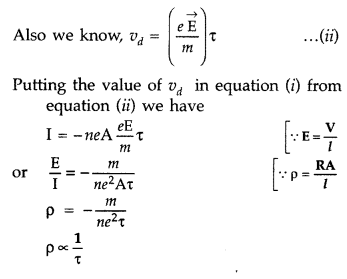
Question 132.
(i) Derive an expression for drift velocity of electrons in a conductor. Hence deduce Ohm’s law.
(ii) A wire whose cross-sectional area is increasing linearly from its one end to the other, is connected across a battery of V volts. Which of the following quantities remain constant in the wire?
(a) drift speed
(b) current density
(c) electric current (d) electric field Justify your answer. (Delhi 2016)
Answer:
(i)
(a) Relation between electric current and drift velocity : Consider a uniform metallic wire XY of length l and cross-sectional area A. A potential difference V is applied across the ends X and Y of the wire. This causes an electric field at each point of the wire of strength :

Due to this electric field, the electrons gain a drift velocity V
d
opposite to direction of electric field. If q be the charge passing through the cross-section of wire in t seconds, then, current in wire, I = \(\frac{q}{t}\)
The distance transversed by each electron in time (t) = drift velocity × time = V d t
If we consider two planes P and Q at a distance V d t in a conductor, then the total charge flowing in time t will be equal to the total charge on the electrons present within the cylinder PQ.
The volume of this cylinder = cross sectional area × length = A V d t
If n is the number of free electrons in the wire per unit volume, then the number of free electrons in the cylinder = n(A V
d
t)
If charge on each electron is -e (e = 1.6 × 10
-19
C), then the total charge flowing through a cross-section of the wire,

This is the relation between electric current and drift velocity. Negative sign shows that the direction of current is opposite to the drift velocity.
(b) Charge = Current × time
(i) For 0 to 5 seconds, the current
![]()
Hence, q
1
= (2.5) × (5) = 12.5 C
(ii) For 5 sec to 10 sec, the current = 5A
Hence, q
2
= 5 × (10 – 5) = 5 × 5 = 25 C
q = q
1
+ q
2
= 12.5 + 25 = 37.5 C
(ii) (c) Electric current will remain constant in the wire.
Reason : All other quantities depend on the cross sectional area of the wire and hence will not remain constant.
Question 133.
(a) State the two Kirchhoff’s laws. Explain briefly how these rules are justified.
(b) The current is drawn from a cell of emf E and internal resistance r connected to the network of resistors each of resistance r as shown in the figure. Obtain the expression for
(i) the current drawn from the cell and
(ii) the power consumed in the network. (Delhi 2016)
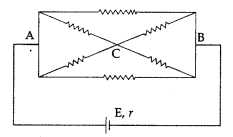
Answer:
(a) Junction Rule : At any Junction, the sum of currents, entering the junction, is equal to the sum of currents leaving the junction.
Loop Rule : The Algebraic sum of changes in potential, around any closed loop involving resistors and cells, in the loop is zero.
![]()
Justification : The first law is in accordance with the law of conservation of charge. The second law is in accordance with the law of conservation of energy.
(b) Given : EMF = E, internal resistance = r, resistance of each resistor = r
The equivalent circuit diagram is shown below
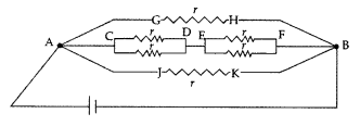
(i) The two resistances of V each between points C and D are in parallel

Similarly two resistances between points E and F are in parallel,
![]()
Now these resistances r
CD
and r
EF
are in series,
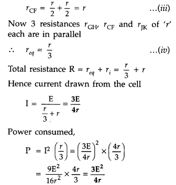
Question 134.
(a) Draw a circuit diagram of a meter bridge used to determine the unknown resistance R of a given wire. Hence derive the expression for R in terms of the known resistance S.
(b) What does the term ‘end error’ in a metre bridge circuit mean and how is it corrected? How will the balancing point be affected, if the positions of the battery and galvanometer are interchanged in a metre bridge experiment? Give reason for your answer. (Comptt. Delhi 2016)
Answer:
(a)
Metre Bridge is special case of Wheatstone Bridge
It is a device based on Wheatstone bridge to determine the unknown resistance of a wire. Principle : Meter bridge is based on the principle of wheatstone bridge, i.e. when bridge is balanced

Circuit : To find the unknown resistance S, the circuit is completed as shown in figure. The unknown resistance wire of resistance S is connected across the gap between points C and D and a resistance box (R) is connected across the gap between the points A and D. A cell, a rheostat and a key (K) is connected between the point A and C by means of connecting screws. In the experiment when the sliding jockey touches the wire AC at any point, then the wire is divided into two parts. These two parts AB and BC act as the resistances P and Q of the Wheatstone bridge. In this way the resistances of arms AB, BC, AD and DC form the resistances P, Q, R and S of Wheatstone bridge. Thus the circuit of meter bridge is the same as that of Wheatstone bridge.

Method : To determine the unknown resistance first of all key K is closed and a resistance R is taken in the resistance box in such a way that on pressing jockey B at end points A and C, the deflection in galvanometer is on both the sides. Now jockey is slided on wire at such a position that on pressing the jockey on the wire at that point, there is no deflection in the galvanometer G. In this position the points B and D are at the same potential, therefore the bridge is balanced. The point B is called the null point. The length of both parts AB and BC of the wire are read on the scale. The condition of balance of Wheatstone bridge is,

If r is the resistance per cm length of wire AC and l cm is the length of wire AB, then length of wire BC will be (100 – l) cm
∴ P = resistance of wire AB = lr
Q = resistance of wire BC = (100 – l)r
Substituting these values in equation (i), we get
![]()
As the resistance (R) of wire (AB) is known, the resistance S may be calculated.
A number of observations are taken for different resistances taken in resistance box and S is calculated each time and the mean value of S is found.
(b) The error which arises on account of resistance of copper strips and the connecting wire at both ends of the meter bridge is called end error.
It is minimized by adjusting the balance point near the middle point of the bridge.
• The balancing point will not be affected, as the bridge remains balanced.
Question 135.
(a) State the working principle of a potentiometer with help of a circuit diagram, explain how the internal resistance of a cell is determined.
(b) How are the following affected in the potentiometer circuit when
(i) the internal resistance of the driver cell increases and
(ii) the series resistor connected to the driver cell is reduced? Justify your answer. (Comptt. Delhi 2016)
Answer:
(a) Potentiometer principle : When a constant current flows through a wire of uniform cross sectional area, the potential difference, across any length, is directly proportional to the length.
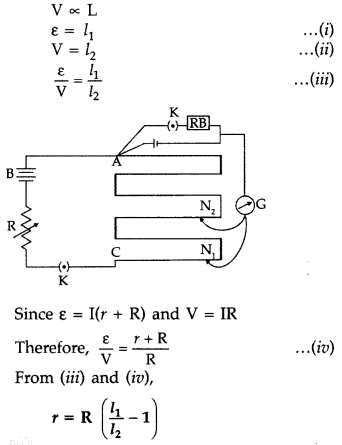
(b) As per CBSE guidelines this question is incomplete hence NOT attempted.